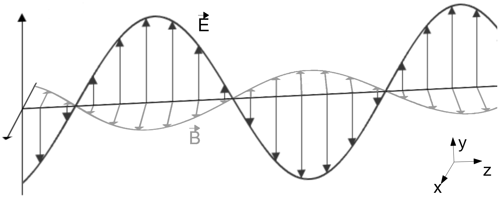
Electromagnetic radiation (EM) is a transverse wave in which the disturbances of magnetic field propagate transversely to the direction of wave propagation, not in parallel, as in longitudinal waves (e.g. sound waves). The directions of oscillations of electric (E) and magnetic (B) field vectors are always perpendicular to each other and to the wave vector (direction of wave propagation).
Fig. 1. Electromagnetic wave diagram: x, y, z directions in space, E - electric vector component, B = magnetic vector component
Considering all the concepts defining the electromagnetic phenomena and the fact that the electric and magnetic fields are inseparable (one field induces the other), only the electric component will be discussed further. The discussion of the magnetic component is similar based on its perpendicularity in relation to the electric component.
A systematic relationship between the direction of the electric field vector’s oscillation (E) in an electromagnetic wave and the direction of wave propagation is referred to as the polarisation.
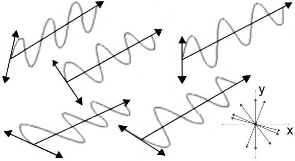
The sources of electromagnetic waves include changes associated with the electrical charge: electron excitation, particle and ionized atoms oscillations, as well as an ordered flow of electric charges in the conductors. The oscillations of the electric field vector in the electromagnetic wave radiated by the source have the same amplitude (single source, e.g. excited sodium atoms in sodium discharge lamps), in all possible directions perpendicular to the direction of wave propagation (different spatial orientation of the source components, e.g. position of the sodium atoms in the discharge tube). It means that a non-polarized electromagnetic wave is in fact a random superposition of many polarized waves.
Fig. 2. The electric component of the non-polarized electromagnetic wave: isometric view and orthogonal view in relation to the direction of wave propagation
The type of electromagnetic wave polarization is indicated by the shape of the vector end E on a plane perpendicular to the direction of wave propagation. Three main types of polarization are defined in the literature: linear, circular and elliptical.
The linear polarization can be observed when the oscillations of the electric field vector propagate in a single plane and are not time-dependant. The vertical polarization V, referred to as EV vector, can be observed in a beam of horizontal electromagnetic waves when the disturbances of the electric field oscillate in the direction perpendicular to the Earth’s surface.
Fig. 3. Vertically polarized electromagnetic wave: (a) view of the plane perpendicular to the direction of wave propagation, (b) isometric view
The horizontal polarization H, referred to as EH vector, can be observed when the oscillations of the vector are parallel to the Earth’s surface.
Fig. 4. Horizontally polarized electromagnetic wave: (a) view of the plane perpendicular to the direction of wave propagation, (b) isometric view
The electric field vectors are added together as per the vector addition rules. If the beam of electromagnetic waves is both vertically and horizontally polarized, the linear polarization is observed when the wave frequencies and direction of wave propagation are identical, and the constituent vibrations are coincident in phase or are displaced in phase by ±180°. The angle of inclination of the resultant electromagnetic wave polarization changes depending on the amplitudes of the constituent waves. The angle of inclination in relation to the Earth’s surface is 45° for identical amplitudes and coincident phases.
Fig. 5. The resultant electromagnetic wave (blue) with linear polarization at an angle of 45°: (a) view of the plane perpendicular to the direction of wave propagation, (b) isometric view
The circular polarization can be observed when the electric field vector, as viewed from the plane perpendicular to the electromagnetic wave front is constant, and its direction changes in time at constant angular velocity. The vector E describes a full circle in a single wave period.
Circular polarization can be achieved by:
rotating the source of the linearly polarized electromagnetic wave around the axis parallel to the direction of propagation; the source should rotate at constant angular velocity;0
transmitting a beam of electromagnetic waves at a specific angle through an oriented transparent medium, e.g. a quarter-wave plate in optics;
reflecting linearly polarized electromagnetic waves from the surfaces of conductive materials at a specific angle; it is a special case of the Faraday effect;
superposing vertically and horizontally polarized electromagnetic waves (or any other electromagnetic waves with linear-orthogonal polarizations perpendicular to each other); frequency, direction and amplitude of propagated waves must be identical; however, the component oscillations are displaced in phase by ±90°.
The phase displacement (+90° or -90°) determines right-hand or left-hand circular polarization of the electromagnetic wave. In optics, the electromagnetic wave is right-hand polarized, if the wave propagates in the direction of the observer and the end of the electric field vector rotates clockwise.
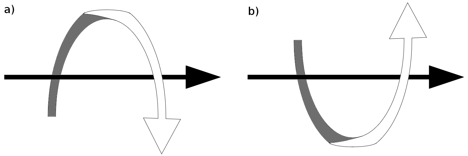
Fig. 6. The resultant electromagnetic wave (blue) with right-hand circular polarization (as per the definition used in optics): (a) view of the plane perpendicular to the direction of wave propagation, (b) isometric view
Left-hand polarized wave propagates in the direction of the observer, and the E vector rotates counterclockwise.
Fig. 7. The resultant electromagnetic wave (blue) with left-hand circular polarization (as per the definition used in optics): (a) view of the plane perpendicular to the direction of wave propagation, (b) isometric view
However, in radio engineering, the wave is right-hand polarized, if the wave propagates in the opposite direction and the end of the electric field vector rotates clockwise. A description as per the definition used in radio engineering will be used in the further discussion (developed in 1942 by IRE, currently IEEE). A superposition of right-hand and left-hand circularly polarized electromagnetic waves with coinciding amplitudes and phases produces a resultant vertically polarized electromagnetic wave. A displacement in phase by ±90° will produce a horizontally polarized electromagnetic wave.
Fig. 8. The superposition of left-hand and right-hand circularly polarized electromagnetic waves. The resultant vertically polarized electromagnetic wave (blue): (a) view of the plane perpendicular to the direction of wave propagation, (b) isometric view
The elliptical polarization can be observed when the electric field vector, as viewed on the plane perpendicular to the face of the propagating wave, changes its direction (angular velocity does not have to be constant in time) and amplitude. In a single period, E vector describes a full circle around the direction of electromagnetic wave propagation. Similar to circular polarization, the elliptical polarization can be in one of two possible states, right-hand elliptical polarization, and left-hand circular polarization.
Fig. 9. Projection of the resultant electric field vector (blue) on a plane perpendicular to the direction of electromagnetic wave propagation. Elliptical polarization: (a) right-hand, (b)left-hand
Since the circular (and linear) polarization is a special case of elliptical polarization, the methods to achieve the polarization are also similar with slight changes:
rotating the source of linearly polarized electromagnetic wave at variable angular velocity;
linearly polarized electromagnetic waves are reflected from metallic surfaces at any angle (except for the angle of circular polarization);
superposing polarized electromagnetic waves:
- linearly-orthogonally polarized waves (phase displacement and different amplitudes),
- left-hand circularly polarized and right-hand circularly polarized waves (phase displacement and/or different amplitudes),
- circularly polarized wave with linearly polarized wave.
Let’s discuss vertically and horizontally polarized electromagnetic waves at coinciding amplitudes, identical frequencies and parallel direction of propagation. A linear polarization is a superposition at coincident phases. A displacement in phase from 0° to 90° produces a right-hand elliptical polarization until a right-hand circular polarization is achieved at 90° phase displacement. Further displacement in phase from 90° to 180° produces a circular polarization, through elliptical polarization to linear polarization at 180°. The effect is identical at 180° → 270° → 360° however, the polarization changes from right-hand to left-hand. At a phase displacement of 360°, the polarization returns to its initial state.
Fig. 10. Projection of the resultant electric field vector (blue) on a plane perpendicular to the direction of electromagnetic wave propagation. Change in polarization state due to the increase in phase displacement between the electromagnetic wave components. The direction of circular and elliptical polarization is shown by a red arrow.
Changes in polarization are equivalent for the superposition of right-hand and left-hand circularly polarized electromagnetic wave.
All electromagnetic waves from natural sources (and most electromagnetic waves from artificial sources) are non-polarized. Several physical phenomena (transmission through a dielectric medium, reflection from a dielectric or conductor, Rayleigh scattering) may give preference to a specific direction of the electric field vector oscillations. As a result, a partially polarized beam of electromagnetic waves can be produced. In certain cases (multiple transmission through dielectric, transmission through electromagnetic radiation separating material with orthogonal polarization, doubly refracting materials, reflection from metallic surface or at a Brewster angle) may lead to a complete polarization of the electromagnetic wave.
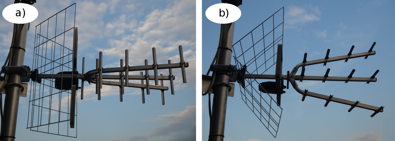
Thus, the polarisation of electromagnetic waves from natural sources is always secondary in nature. The polarization of electromagnetic waves from artificial sources is mostly used in the radio frequency range. Linear polarization is used in terrestrial television and radio signals, as well as WiFi networks. Most European countries including Czech Republic, France, Spain, Germany, Poland and United Kingdom use DVB-T signal transmitted in horizontal polarization.
Fig. 11. 17/21-60/TRIDIGIT directional antenna (Yagi-Uda type) set to receive a terrestrial television signal transmitted in: (a) vertical, (b) horizontal polarization
Propagation of the electromagnetic waves in the lower atmosphere layers (tropospheric propagation) may lead to rotation of the polarization plane due to the signal reflected from different surfaces, e.g. roofs. The signal reflected or transmitted through the upper atmosphere layers (ionospheric propagation) may also lead to rotation of the polarization plane (strongly dependent on the wavelength), the reversal of the polarisation direction from left-hand to right-hand (and vice versa) and/or change from linear to elliptical polarization (Faraday effect).
The receiving antenna should be positioned in the same plane as the transmitting antenna (linearly polarized waves) or should have a proper direction (circularly and elliptically polarized waves) to prevent attenuation in polarization (incompatible polarization of the receiving antenna and the polarization of the incoming signal).
The attenuation of linearly polarized wave increases with the increase in angle between the polarization planes. The maximum attenuation is observed for the signal transmitted in orthogonal polarization (signal strength drops by up to 30 dB). The antennas for circular polarization are often used to minimize this effect. The reception of right-hand circularly polarized wave by the antenna for receiving left-hand circularly polarized waves is also associated with high attenuation. Turnstile antennas are often used instead of single helical antennas to maintain a stable signal attenuated by 3 dB, irrespective of the polarization of the received wave.
In most cases, satellite television signal is transmitted by circularly polarized electromagnetic waves. The circular polarization is used as a superposition of linearly-orthogonally polarized waves to double the number of transmitted channels by modulating a separate television channel for each wave component.
Advanced radar techniques use electromagnetic waves in different polarization states depending on the expected results. Linear polarization can also be used for detecting metal objects (an elliptically polarized wave is reflected) or meteorological observations. Circular polarization can be used to reduce the attenuation caused by the presence of water (fog, clouds or rain).
Polarization of electromagnetic waves is also used in many fields of science including astronomy (e.g., to detect water in the rings of Saturn or microwave background radiation), biology (e.g., study of the structure and size of viruses), chemistry (e.g. to detect enantiomers), medicine and nuclear physics (e.g., to study nuclei), and also in light and heavy industry (polarimetry and flaw detection), entertainment (3D projections) or products for daily use (LCD displays and sunglasses).
Electromagnetic radiation travels both in waves and as a stream of particles (photons). The concept of electromagnetic wave polarization as per the definition used in the classical electrodynamics has its equivalent in the photon spin quantum number. Each quantum of the electromagnetic radiation is characterized by its energy (frequency), phase and spin with a value of 1 or -1, and the spin axis is always parallel to the direction of wave propagation. Right-hand and left-hand spin are used alternatively.
Linear polarization of the electromagnetic wave can be observed when a stream includes photons in both right and left spin state with the same probability. Right-hand circular polarization is related to the prevalence of photons in a right spin state; and it is opposite in left-hand circular polarization. Non-polarized electromagnetic wave corresponds to a beam of photons which are different superpositions of 1 and -1 state of the spin quantum number.
Net:
0.00
EUR
Gross:
0.00
EUR
Weight:
0.00
kg
This site uses cookies. More information about using by us cookie files, their usage and how to modify the acceptance of cookie files, can be found by pressing
link
 English
 Български
 Český
Český Dansk
Dansk Deutsch
 Eesti
Eesti Ελληνικά
 Español
 Français
 Italiano
 Latviešu
  Lietuvių
  Magyar
 Nederlands
 Polski
 Português
 Pусский
 Română
 Slovenski
 Slovenský
 Suomi
Suomi Svenska
 EUR
EUR AUD
AUD CAD
CAD CHF
CHF CZK
CZK DKK
DKK GBP
GBP HUF
HUF NOK
NOK PLN
PLN SEK
SEK USD
USD
 Home
Home Contact
 New products