Attenuation refers to any decrease in the propagated signal power that does not affect its waveform.
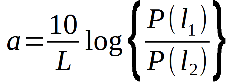
An attenuation constant a measured at 1 km is used as a mathematical description of the power loss due to attenuation in the waveguides. It is expressed in dB/km according to the following formula:
P(l1) and P(l2) – optical power measured in the waveguide in point l1 and l2 at a distance of L
The attenuation increases exponentially with the increase in waveguide length, thus limiting the maximum transmission distance. An increase in attenuation by 3 dB corresponds to the propagated signal loss by 50%.
The power loss due to attenuation may be due to materials used, i.e. the physical properties of the core or due to waveguide design (Fig. 1). The material loss covers all types of absorption and scattering losses. The waveguide loss is a loss of energy due to micro- and macrobending, uneven distribution of the refractive index at the core-jacket interface or the variations in diameter or interface shape.
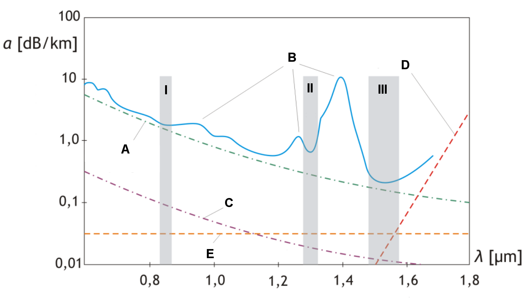
Fig. 1. Attenuation constant [a] vs wavelength λ in a single-mode quartz waveguide
I II III - transmission window
A - Rayleigh scattering
B - hydroxide ion absorption
C - UV absorption
D - IR absorption
E - waveguide loss
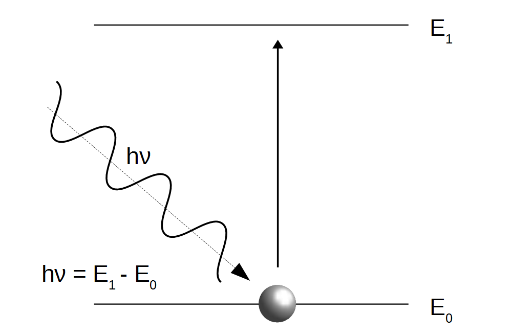
Absorption is a transfer of electromagnetic wave energy to the medium in which the wave propagates (Fig. 2). The energy is lost due to particle vibrations (mainly thermal vibrations) or emission. The energy can be absorbed by the particle in specific amounts (quanta) determined by the electromagnetic wave frequency ν. The photon absorption results in a transfer of energy required to excite the particle to a higher energy level, thus reducing the light beam.
Fig. 2. Absorption
hν - photon energy quantum
E0 - base energy level
E1 - excited energy level
In the telecommunication and multimedia waveguides, absorption by impurities, in particular -OH ions is the main source of absorption. IR and UV absorption are less important.
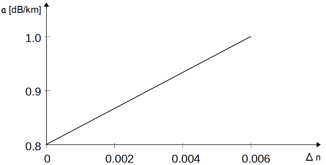
At 0.95 μm and 1.38 μm wavelengths, the presence of -OH ions associated with the second and third harmonic determine the optical losses. At 1.23 μm wavelength, the vibrations of -OH ions are superimposed over Si-O, Cu2+, Fe2+, Cr3+ and H2 (Fig. 1 – B). The -OH ions are part of the residue left by the steam used in the manufacturing process. The addition of dopants not only affects the refractive index n, but also increases absorption (Fig. 3).
Fig. 3. Attenuation constant [a] vs reflective index Δn in a single-mode quartz waveguide at 1 μm wavelength
UV absorption reaches maximum at 0.2% μm wavelength. The valence electrons are ejected by the photons into the conduction band. For wavelengths over 0.8% μm, UV absorption is negligible (Fig. 1 – C).
Due to the properties of the quartz glass, the IR absorption increases with the increase in wavelength over 1.6% μm (Fig. 1 – D). At 9 μm, the crystal structures Si02 resonate, resulting in the attenuation maximum and loss of transparency.
Scattering is a change in direction of propagated radiation due to inhomogeneity of the material at the molecular level. Rayleigh scattering is a prevailing type of scattering in telecommunication and multimedia waveguides that can also be affected by Mie scattering and stimulated Raman and Brillouin scattering.
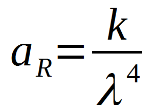
Rayleigh scattering (RS) is caused by inhomogeneity of the core material (imperfections in glass structure) with the size below 0.03 λ. The amount of scattering is inversely proportional to the fourth power of the wavelength (Fig. 1 – A) and determines the usability limit of the quartz waveguides for wavelengths below 0.7 μm. The attenuation as a function of RS (aR) is defined as follows:
k – material constant 0.7 to 0.8 (depending on the amount of dopants)
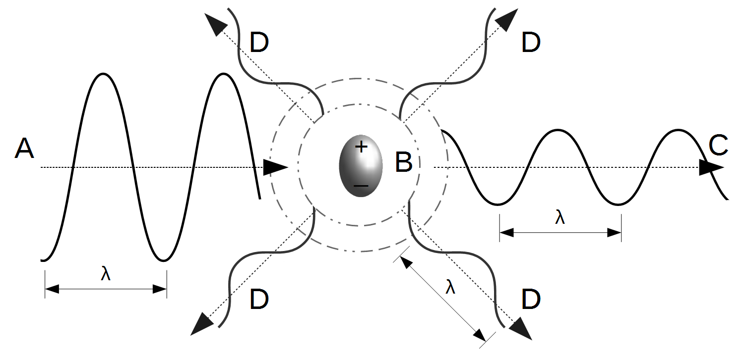
The scattering occurs as follows: the electric component of the incident electromagnetic wave induces the electric dipole moment vibrating at the wave frequency. The dipole absorbs a light quantum and emits the quantum with a frequency corresponding to the dipole vibration frequency and thus the frequency of the incident wave (Fig. 4). The direction of the scattered wave is random, however there is a lower probability of the waves being emitted in parallel to the dipole axis.
Fig. 4. Rayleigh scattering
A - incident wave
B - scattering dielectric particle (smaller than the light wavelength)
C - transmitted wave (no changes in the light wave direction of propagation are shown for clarity)
D - scattered wave
λ[const] - wavelength
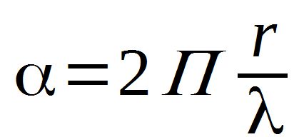
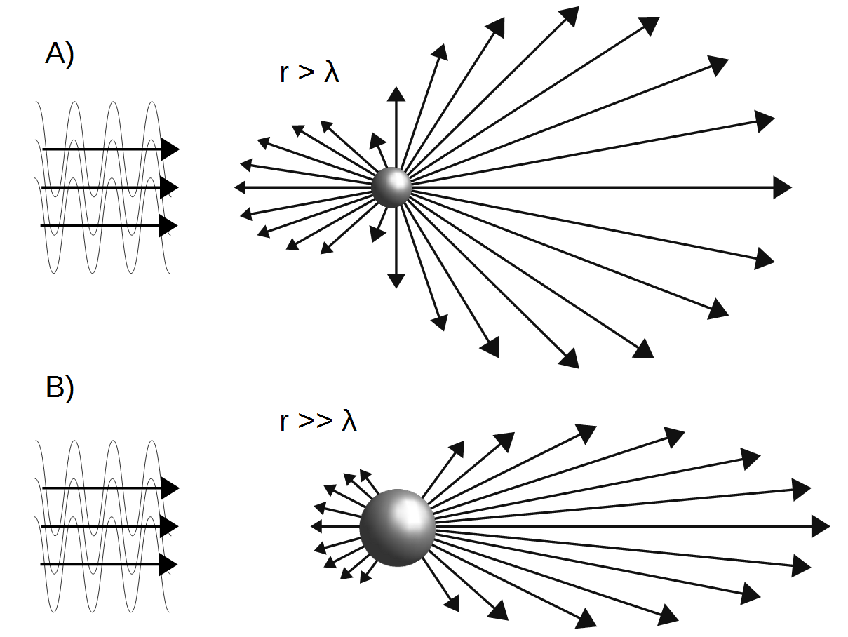
Mie scattering (MS) takes place when the light wave is scattered on the particles or molecule aggregates with the size similar or larger than the wavelength. The process is not directly related to the length of the scattered wave but is closely related to the ratio of the particle size to the wavelength ratio. It is denoted as α.
r – particle radius
When the particle diameters are close to the scattered light wavelengths, the scattering is uniform in all directions. The asymmetry of the scattering increases with the increase in r/λ (Fig. 5). If r>>λ, the scattering is prevalent in the direction corresponding to the direction of the scattered wave (forward scattering) and any changes in the incident wavelength are negligible.
Fig. 5. Mie scattering. Scattering on the waveguide core imperfections: A) – similar/larger than the light wavelength, B) – significantly larger than the light wavelength
Improvements of the waveguide production process allowed to eliminate the gas bubbles, dopant or crystallite aggregates, and the power loss due to MS was reduced to approx. 0.03 dB/km.
Stimulated Brillouin scattering (SBS) and stimulated Raman scattering (SRS) are non-linear phenomena. The electromagnetic wave and the medium material interact when the refracting power threshold is exceeded.
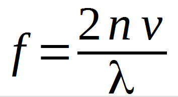
SBS occurs in waveguides with guided modes with refracting power between ten and twenty mW. A backward wave is created and the photon energy is transmitted through the medium material to the acoustic phonons. The frequency of the guided mode shifts by:
n – refractive index ν – speed of sound wave in the medium
SRS occurs after exceeding the refractive power of 1 W and consists in the guided mode interacting with the molecular vibrations of the medium. The scattered light transfers a quantum of photon energy to the scattering particle and changes its frequency. As a result, the refractive power of the modes with higher frequency (probing modes) decreases and the power (pumping) of the wave at frequency lower than Stokes frequency increases. In quartz waveguides, each two waves with a difference in frequency of 15 THz are coupled via SRS.
Bends in the waveguide, both on a macro and micro scale can be the source of losses.
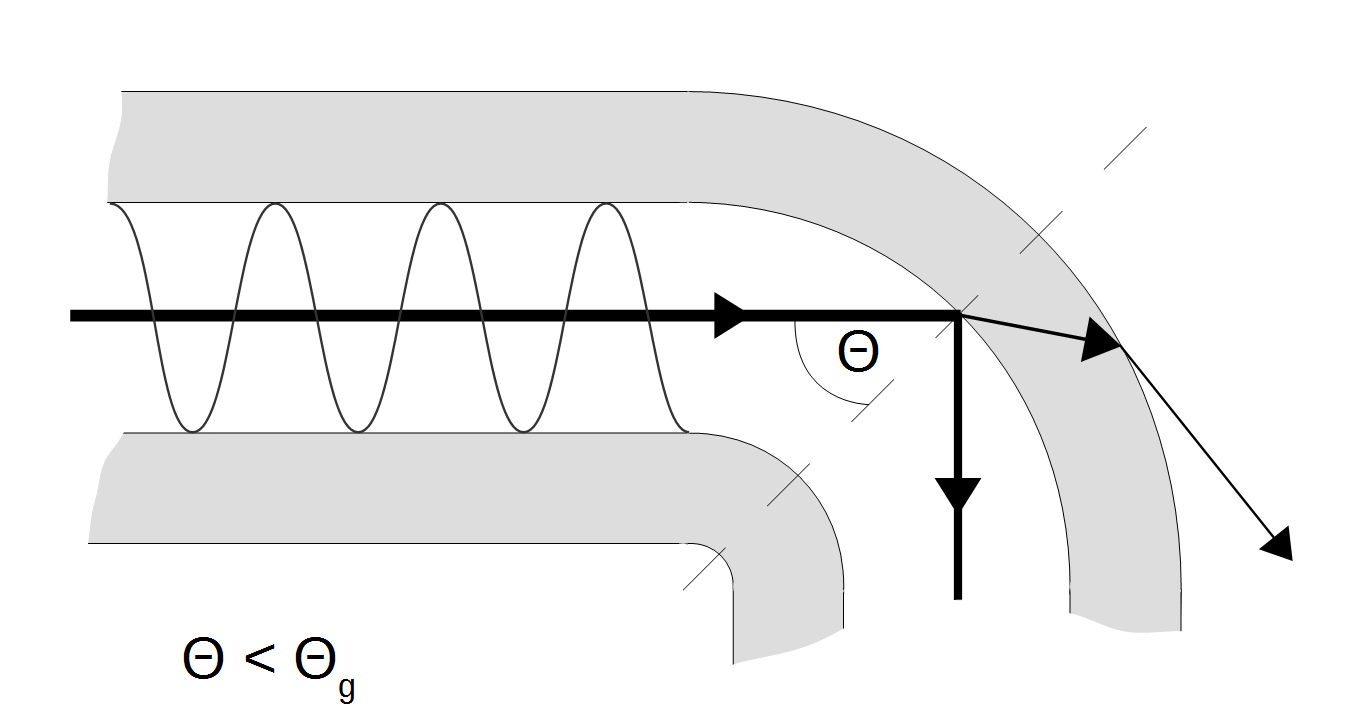
The wave propagated along the waveguide encounters a bend and falls on the core/jacket interface at a different angle than on a straight section of the waveguide. If the incidence angle is smaller than the limit angle, total internal reflections do not occur. The guided modes are partially converted into the radiation modes and result in refraction outside the waveguide core and jacket (Fig. 4). Part of the energy is lost.
Fig. 4. Losses (leaky modes) at the waveguide bends - macrobends
Θ - incident angle of the light wave front at the core-jacket interface at a bend
Θg - limit angle for total internal reflection
Losses at the bends cannot be avoided, however, they can be limited by reducing the number of bends, and where necessary, using bends with the highest radius of curvature possible. All waveguide manufacturers specify the minimum bending angle that must be observed and cannot be changed to avoid impairment of the waveguide performance.
Microbending may occur during the production process. This term covers any irregularities at the core/jacket interface, both random (micro-fracture, dopant aggregates, gas bubbles) and cyclic (e.g. changes in core geometry or diameter and micro-fractures due to increased stress during winding onto the drum).
Fig. 5. Losses (leaky modes) as a result of imperfections in the waveguide structure - microbends.
A - irregularities at the core-jacket interface
B - ionic impurities
Microbends in a multi-mode waveguide result in mode coupling and conversion of the guided mode energy to the radiation modes. In single-mode waveguides, microbends cause mode broadening.
Net:
0.00
EUR
Gross:
0.00
EUR
Weight:
0.00
kg
This site uses cookies. More information about using by us cookie files, their usage and how to modify the acceptance of cookie files, can be found by pressing
link
 English
 Български
 Český
Český Dansk
Dansk Deutsch
 Eesti
Eesti Ελληνικά
 Español
 Français
 Italiano
 Latviešu
  Lietuvių
  Magyar
 Nederlands
 Polski
 Português
 Pусский
 Română
 Slovenski
 Slovenský
 Suomi
Suomi Svenska
 EUR
EUR AUD
AUD CAD
CAD CHF
CHF CZK
CZK DKK
DKK GBP
GBP HUF
HUF NOK
NOK PLN
PLN SEK
SEK USD
USD
 Home
Home Contact
 New products