A coaxial cable is the most commonly used aerial cable. It is also referred to as the aerial cable or “coax” - due to its design.
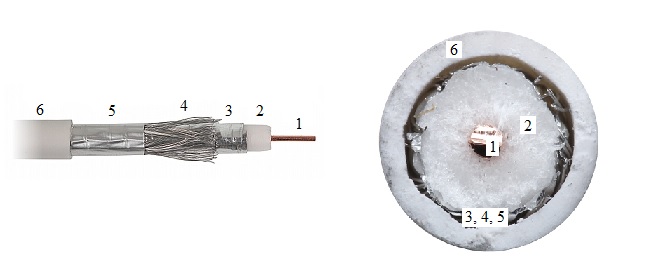
Fig. 1. Example coaxial cable
1 - copper core (conductor) 2 - dielectric (insulator) 3 - aluminium or copper film 4 - woven shield 5 - protective film 6 - outer sheath
The effective signal is transmitted over a copper core. An insulator separates the core from a woven shield. An aluminium film is an additional cable shield. The woven shield insulates the electromagnetic field generated by the core, to prevent its emission outside and thus affecting the operation of other devices. The woven shield also separates the effective signal from the external interfering electromagnetic field. The shield improves the cable’s resistance to interference and crosstalk.
The crosstalk take place when one cable interferes with another cable introducing undesirable signals. It may distort images (TV signal) and result in a low quality image.
To ensure correct operation of the network, the coaxial cable should not introduce any attenuation loss. However, all components used in the signal transmission have specific physical and electrical properties, e.g.:
Attenuation loss, expressed in decibels per 100 m [dB/100m], determines the ratio of signal power at the beginning of the transmission route (cable) to signal power at a specific distance from the beginning of the transmission route (e.g. at 100 m).
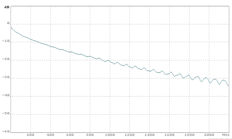
The attenuation loss of the cable is affected by the cable age, humidity, signal frequency and core material. The higher the frequency, the higher the attenuation loss (Fig. 2). To prevent losses, use of high quality coaxial cables is recommended (higher costs).
Fig. 2. Example amplitude-frequency characteristic of the cable attenuation loss per 100 m; 0 to 2,000 MHz.
The attenuation loss depends on the cable design, i.e. thickness and quality of materials, directly affecting losses in the core and in the dielectric insulator. Additional losses due to wear and tear (e.g. material fatigue) depend on moisture absorption and cable age. The attenuation loss of the transmission line defines the frequency of the devices transmitting and receiving the signals.
Wave impedance, expressed in Ohms [Ω] determines the ratio of the alternating voltage at the input to the current ratio. Wave impedance depends on cable geometry, its design and materials used. The impedance of a standard aerial cable is 50 Ω or 75 Ω.
Standing Wave Ratio (SWR) determines the degree in which the aerial is matched to the power line. It is a ratio of the maximum amplitude to the minimum amplitude and thus it is a non-dimensional value. Standard SWR is between 1 and infinity [∞].
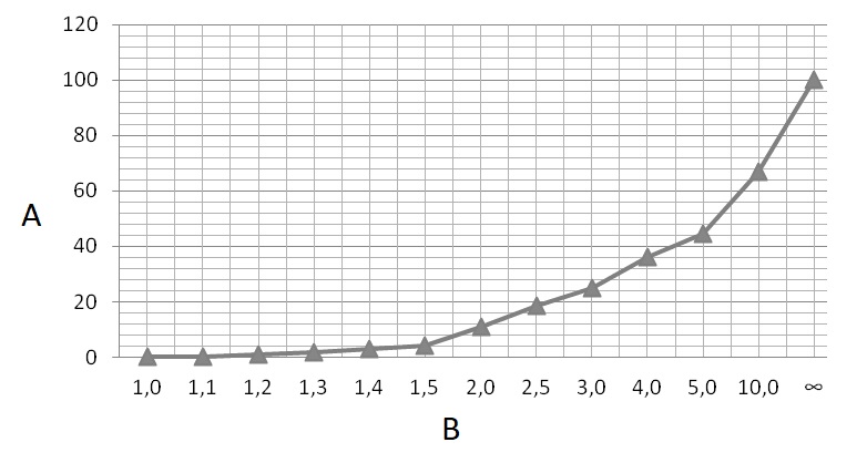
Fig. 3. Relationship between % reflected wave and SWR
A - % reflected wave B - WFS
Preferably, SWR should be 1, which means that the aerial’s impedance is equal to the power line’s impedance and thus the impedances are matched. The signal power is 100% transmitted without any reflections of the effective wave. 25% signal power is reflected at SWR = 3. In practice, the transmission is possible up to SWR = 2.
The higher the mismatch, the higher the signal returned to the transmitter and the lower the signal received by the receiver. In practice, a correct impedance is of the utmost importance. In extreme cases, impedance mismatch may affect the transmitted power.
Braid density, expressed as a percentage [%] – the higher the braid density the better is the shielding effectiveness of the cable. In practice, the more wires are used to form the braid, the higher the braid density.
Shielding effectiveness, expressed in decibels [dB] – is a ratio of the electric or magnetic field without shielding to the electric or magnetic field outside the shielded cable. In practice, if the shielding effectiveness is sufficient, several coaxial cables can be used adjacent to each other without any interferences.
The attenuation of coaxial cables and the density of their braid is of great importance in electrical installations in residential buildings. In such places, when choosing the cabling for the installation, keep in mind the current Regulation of the Minister of Infrastructure of April 22, 2002 (the position of the Minister of Infrastructure was in force until October 31, 2005, as of today the role of the Minister of Infrastructure is fulfilled by the Minister of Infrastructure and Construction) on technical requirements for buildings and their location (consolidated text, Journal of Laws 2015, item 1422).
In the context of this article the most important is § 192f point 6, which states that in an aerial collective installation used to receive digital television and radio programs distributed in a terrestrial way, it is necessary to use: "coaxial cables of RG-6 category or higher, made in Class A, containing a double screen - aluminum foil and braid with a density of at least 77% and a copper inner core with a diameter of not less than one millimeter, where damping of each track created from coaxial cables should not exceed 12 dB at 860 MHz".
Advantages:
resistance to interference due to shielding, good quality transmission;
resistance to mechanical damage;
good impedance matching;high shielding effectiveness.
Disadvantages:
low quality aerial cables are not resistant to weather conditions resulting in reduced physical and electrical parameters;
limited data transfer rate - up to 10 Mb;
low quality cables may be difficult to fit with BNC connector due to low quality materials used.
Net:
0.00
EUR
Gross:
0.00
EUR
Weight:
0.00
kg
This site uses cookies. More information about using by us cookie files, their usage and how to modify the acceptance of cookie files, can be found by pressing
link
 English
 Български
 Český
Český Dansk
Dansk Deutsch
 Eesti
Eesti Ελληνικά
 Español
 Français
 Italiano
 Latviešu
  Lietuvių
  Magyar
 Nederlands
 Polski
 Português
 Pусский
 Română
 Slovenski
 Slovenský
 Suomi
Suomi Svenska
 EUR
EUR AUD
AUD CAD
CAD CHF
CHF CZK
CZK DKK
DKK GBP
GBP HUF
HUF NOK
NOK PLN
PLN SEK
SEK USD
USD
 Home
Home Contact
 New products