AWG (American Wire Gauge) – is an American standardized system for determining diameters or cross-sectional areas of wires.
AWG is expressed as integer value (e.g. 1, 2 or 15) corresponding to a specific dimension (in mm, inches, mm2 or kcmil). Within this system, increasing gauge numbers denote decreasing wire size. Example: 1 AWG = 42.40 mm2, whereas 28 AWG = 0.32 mm2.
Fig. 1. Approximate ratio (in a suitable scale) of different wire sizes in AWG standard
AWG standard has been developed at the beginning of the 19th century, with its final version developed in 1957 by Joseph Rogers Brown for Browne & Sharpe - a manufacturer of measuring instruments. AWG is also called Brown and Sharpe wire gauge (B&S).
The inverse order of the AWG is due to the wire production process used at the time the system has been developed. At first, AWG corresponded to the number of drawing operations used to produce a given gauge of wire on the drawing die. A blank with a 160 kcmil cross-sectional area requires 20 drawing operations through successively smaller dies to reach the desired size - a wire with a 1.02 kcmil (20 AWG) cross-sectional area. The gauges below one (0 [1/0], 00 [2/0], 000 [3/0] and 0000 [4/0]) has been introduced at a later date, and the wires with corresponding dimensions were manufactured from blanks, compacts or cast rods with cross-sectional area over 106 kcmil.
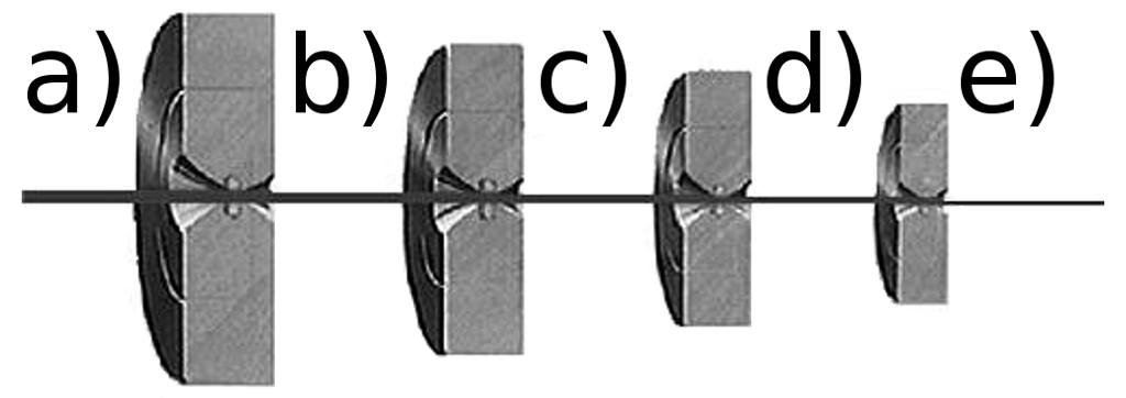
Fig. 2. Changes in gauge number after a single draw of the wire through each die: (a) initial wire, (b) to (d) subsequent gauge wires. Example: (a) = 6 AWG → (e) = 10 AWG
There are 44 gauge sizes: from No. 0000 [4/0] corresponding to the largest wire diameter to No. 40 corresponding to the smallest wire diameter. Each successive gauge number increases cross-sectional area by approx. 20.5% and diameter by approx. 10.25%. The drawing dies used by Brown & Sharpe allowed to reduce the wire diameter by exactly 10.25%.
It leads to the following: – when the cross-sectional area is doubled, the gauge will decrease by 3, e.g. two No. 12 AWG has the same cross-sectional area as a single No. 9 AWG wire; – when the diameter of a wire is doubled, the gauge will decrease by 6, e.g. No. 9 AWG wire is about twice the diameter of No. 15 AWG wire; – when the diameter of a wire is tripled, the gauge will decrease by 10; – when the diameter of a wire is increased fivefold, the gauge will decrease by 14; – when the diameter of a wire is increased tenfold, the gauge will decrease by 20.
Physical properties of the wire materials also impose certain rules. Aluminium wire has a conductivity of approx. 61% of copper. The aluminium wires has the same resistance as a copper wire smaller by 2 AWG sizes.
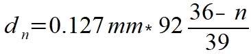
An accurate wire diameter (in mm) for a specific AWG size may be expressed as follows:
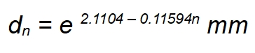
and
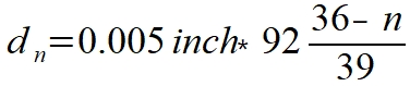
or in inches:
and
where: d – diameter, n – AWG size.
Table 1 shows dimensions and basic physical properties of the various wire gauges.
Table 1. American Wire Gauge (AWG) – dimensions, resistances and maximum ampacity (DC) and a maximum frequency at which the skin effect does not occur (AC). All parameters are based on a copper wire at 25°C
AWG
Diameter
Cross-sectional area
Resistance
Maximum ampacity as:
Maximum frequency for skin depth = 100% area
mm
inch
mm²
kcmil
Ω/km
Ω/kft
GND [A]
power supply [A]
0000 [4/0]
11.684
0.4600
107
212
0.1608
0.04901
380
302
125 Hz
000 [3/0]
10.404
0.4096
85
168
0.2028
0.06180
328
239
160 Hz
00 [2/0]
9.266
0.3648
67.4
133
0.2557
0.07793
283
190
200 Hz
0 [1/0]
8.252
0.3249
53.5
106
0.3224
0.09827
245
150
250 Hz
1
7.348
0.2893
42.4
83.7
0.4066
0.1239
211
119
325 Hz
2
6.544
0.2576
33.6
66.4
0.5127
0.1563
181
94
410 Hz
3
5.827
0.2294
26.7
52.6
0.6465
0.1970
158
75
500 Hz
4
5.189
0.2043
21.2
41.7
0.8152
0.2485
135
60
650 Hz
5
4.621
0.1819
16.8
33.1
1.028
0.3133
118
47
810 Hz
6
4.115
0.1620
13.3
26.3
1.296
0.3951
101
37
1100 Hz
7
3.665
0.1443
10.5
20.8
1.634
0.4982
89
30
1300 Hz
8
3.264
0.1285
8.37
16.5
2.061
0.6282
73
24
1650 Hz
9
2.906
0.1144
6.63
13.1
2.599
0.7921
64
19
2050 Hz
10
2.588
0.1019
5.26
10.4
3.277
0.9989
55
15
2600 Hz
11
2.305
0.0907
4.17
8.23
4.132
1.260
47
12
3200 Hz
12
2.053
0.0808
3.31
6.53
5.211
1.588
41
9.3
4150 Hz
13
1.828
0.0720
2.62
5.18
6.571
2.003
35
7.4
5300 Hz
14
1.628
0.0641
2.08
4.11
8.286
2.525
32
5.9
6700 Hz
15
1.450
0.0571
1.65
3.26
10.45
3.184
28
4.7
8250 Hz
16
1.291
0.0508
1.31
2.58
13.17
4.016
22
3.7
11 kHz
17
1.150
0.0453
1.04
2.05
16.61
5.064
19
2.9
13 kHz
18
1.024
0.0403
0.823
1.62
20.95
6.385
16
2.3
17 kHz
19
0.912
0.0359
0.653
1.29
26.42
8.051
14
1.8
21 kHz
20
0.812
0.0320
0.518
1.02
33.31
10.15
11
1.5
27 kHz
21
0.723
0.0285
0.410
0.810
42.00
12.80
9
1.2
33 kHz
22
0.643
0.0253
0.326
0.642
52.96
16.14
7
0.92
42 kHz
23
0.573
0.0226
0.258
0.509
66.79
20.36
4.7
0.73
53 kHz
24
0.511
0.0201
0.205
0.404
84.22
25.67
3.5
0.58
68 kHz
25
0.455
0.0179
0.162
0.320
106.2
32.37
2.7
0.46
85 kHz
26
0.405
0.0159
0.129
0.254
133.9
40.81
2.2
0.36
107 kHz
27
0.361
0.0142
0.102
0.202
168.9
51.47
1.7
0.29
130 kHz
28
0.321
0.0126
0.0810
0.160
212.9
64.9
1.4
0.23
170 kHz
29
0.286
0.0113
0.0642
0.127
268.5
81.84
1.2
0.18
210 kHz
30
0.255
0.0100
0.0509
0.101
338.6
103.2
0.86
0.14
270 kHz
31
0.227
0.00893
0.0404
0.0797
426.9
130.1
0.70
0.11
340 kHz
32
0.202
0.00795
0.0320
0.0632
538.3
164.1
0.53
0.09
430 kHz
33
0.180
0.00708
0.0254
0.0501
678.8
206.9
0.43
0.07
540 kHz
34
0.160
0.00630
0.0201
0.0398
856.0
260.9
0.33
0.06
690 kHz
35
0.143
0.00561
0.0160
0.0315
1079
329.0
0.27
0.04
870 kHz
36
0.127
0.00500
0.0127
0.0250
1361
414.8
0.21
0.04
1100 kHz
37
0.113
0.00445
0.0100
0.0198
1716
523.1
0.17
0.03
1350 kHz
38
0.101
0.00397
0.00797
0.0157
2164
659.6
0.13
0.02
1750 kHz
39
0.0897
0.00353
0.00632
0.0125
2729
831.8
0.11
0.02
2250 kHz
40
0.0799
0.00314
0.00501
0.00989
3441
1049
0.09
0.01
2900 kHz
Diameters of solid wires and stranded wires of the same AWG size are different, since the diameter/cross-sectional area determines the AWG wire size. Cross-sectional area/diameter of the stranded wire includes wires and gaps between the wires. The gaps depend on the wire layout within the round stranded wire. The AWG gauge of a stranded wire represents the sum of the cross-sectional areas of the individual wires, and not the cross-sectional area of the stranded wire as a whole.
Table 2 shows parameters of a solid wire and a stranded wire. Layout, outer diameter and cross-sectional area (including gaps between wires – not including insulation) and wire resistance (in Ω/km) are compared.
Table 2. Comparison of basic parameters of solid wires and stranded wires (n – number of wires)
AWG
Wire layout
Diameter
Cross-sectional area
Resistance
n/AWG
n x mm
mm
mm²
Ω/km
0000 [4/0]
Single solid wire
11.684
107
0.16
259/21
259 x 0.724
13.259
106.63
0.16
427/23
427 x 0.574
13.259
110.49
0.15
000 [3/0]
Single solid wire
10.405
85.0
0.20
259/22
259 x 0.643
11.786
84.40
0.20
427/24
427 x 0.511
11.786
87.57
0.19
00 [2/0]
Single solid wire
9.266
67.4
0.25
133/20
133 x 0.813
10.516
69.04
0.25
259/23
259 x 0.574
10.516
67.02
0.25
0 [1/0]
Single solid wire
8.251
53.5
0.32
133/21
133 x 0.724
9.347
54.75
0.31
259/24
259 x 0.511
9.347
53.12
0.32
1
Single solid wire
7.348
42.4
0.40
133/22
133 x 0.643
8.331
43.19
0.40
259/25
259 x 0.045
8.331
42.11
0.41
817/30
817 x 0.254
8.331
41.40
0.42
2109/36
2109 x 0.160
8.331
42.40
0.41
2
Single solid wire
6.544
33.60
0.51
133/23
133 x 0.574
7.417
34.42
0.50
259/26
259 x 0.404
7.417
33.20
0.52
665/30
665 x 0.256
7.417
33.70
0.52
2646/36
2646 x 0.127
7.417
33.52
0.52
4
Single solid wire
5.189
21.20
0.82
133/225
133 x 0.455
5.898
21.63
0.80
259/27
259 x 0.363
5.898
26.80
0.66
1666/36
1666 x 0.127
5.898
21.10
0.82
6
Single solid wire
4.115
13.30
1.29
133/27
133 x 0.363
4.674
13.76
1.50
259/30
259 x 0.254
4.674
13.12
1.30
1050/36
1050 x 0.127
4.674
13.32
1.30
8
Single solid wire
3.264
8.37
2.06
49/25
49 x 0.455
3.734
7.96
2.20
133/29
133 x 0.287
3.734
8.60
2.00
655/36
655 x 0.127
3.734
8.30
2.00
10
Single solid wire
2.588
5.26
3.27
37/26
37 x 0.404
2.921
4.74
3.60
49/27
49 x 0.363
2.946
5.07
3.60
105/30
105 x 0.254
2.946
5.32
3.20
12
Single solid wire
2.053
3.21
5.21
7/20
7 x 0.813
2.438
3.63
4.80
19/25
19 x 0.455
2.369
3.09
5.60
65/30
65 x 0.254
2.413
3.29
5.70
165/34
165 x 0.160
2.413
3.32
5.20
14
Single solid wire
1.628
2.08
8.28
7/22
7 x 0.643
1.854
2.238
7.60
19/27
19 x 0.361
1.854
1.945
8.90
41/30
41 x 0.254
1.854
2.078
8.30
105/34
105 x 0.160
1.854
2.111
8.20
16
Single solid wire
1.291
1.310
13.2
7/24
7 x 0.511
1.524
1.440
12.0
19/29
19 x 0.287
1.473
1.229
14.0
26/30
26 x 0.254
1.499
1.317
13.1
65/34
65 x 0.160
1.499
1.310
13.2
105/36
105 x 0.127
1.499
1.330
13.1
18
Single solid wire
1.024
0.823
21.0
7/26
7 x 0.404
1.219
0.897
19.2
16/30
16 x 0.254
1.194
0.811
21.3
19/30
19 x 0.254
1.245
0.963
17.9
41/34
41 x 0.160
1.194
0.824
20.9
65/36
65 x 0.127
1.194
0.823
21.0
20
Single solid wire
0.812
0.518
33.3
7/28
7 x 0.320
0.865
0.562
33.8
10/30
10 x 0.254
0.889
0.507
33.9
19/32
19 x 0.203
0.940
0.615
28.3
26/34
26 x 0.160
0.914
0.523
33.0
41/36
41 x 0.127
0.914
0.520
32.9
22
Single solid wire
0.644
0.326
53.0
7/30
7 x 0.254
0.762
0.355
48.4
19/34
19 x 0.160
0.787
0.382
45.1
26/36
26 x 0.127
0.762
0.330
52.3
24
Single solid wire
0.511
0.205
84.2
7/32
7 x 0.203
0.610
0.227
76.4
10/34
10 x 0.160
0.582
0.201
85.6
19/36
19 x 0.127
0.610
0.241
69.2
41/40
41 x 0.078
0.582
0.196
84.0
26
Single solid wire
0.405
0.129
133.9
7/34
7 x 0.160
0.483
0.141
122.0
19/38
19 x 0.102
0.508
0.155
113.0
10/36
10 x 0.127
0.533
0.127
137.0
28
Single solid wire
0.321
0.081
212.9
7/36
7 x 0.127
0.381
0.087
213.0
19/40
19 x 0.078
0.406
0.091
186.0
30
Single solid wire
0.255
0.050
338.6
7/38
7 x 0.102
0.305
0.057
339.0
19/42
19 x 0.064
0.305
0.061
286.7
32
Single solid wire
0.202
0.032
538.3
7/40
7 x 0.078
0.203
0.034
538.0
19/44
19 x 0.050
0.229
0.037
448.0
34
Single solid wire
0.160
0.020
856.0
7/42
7 x 0.064
0.192
0.022
777.0
36
Single solid wire
0.127
0.013
1362.0
7/44
7 x 0.050
0.152
0.014
1271.0
The table shows a list of AWG sizes from 4/0 [No. 0000] to No. 2 and successive even AWG sizes up to No. 36 incl. Wires with AWG size over 36 are not available as stranded wires, since the wire diameter required would have to be extremely small.
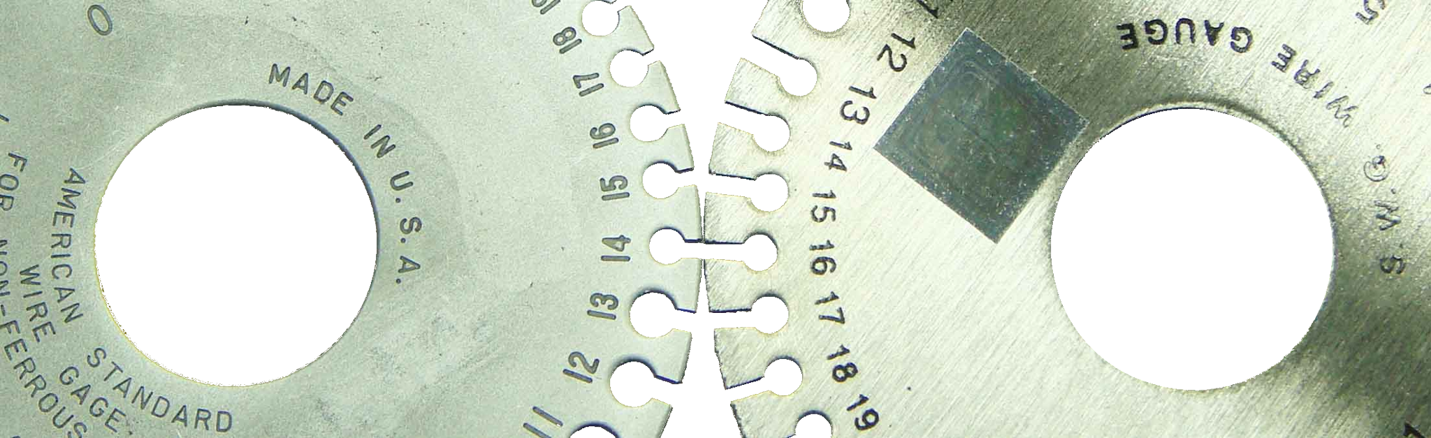
AWG has been developed and initially used in the USA. It is now widely used worldwide, replacing other systems and standards. It has competed with a British Birmingham Wire Gauge (BWG) system, however, at the end of the 19th century, slightly modified BWG has been replaced by Standard Wire Gauge (SWG), now widely used in the UK. SWG is also known as Imperial Wire Gauge or British Standard Gauge. SWG gauges look almost identical to AWG gauges, however the sizes correspond to different wire dimensions.
Fig. 3. Comparison of AWG (left) and SWG (right) wire gauges. No. 14 AWG ≈ No. 16 SWG
Fig. 3 shows No. 14 AWG as nearly equal to No. 16 SWG.
The main difference between AWG and SWG is the material of the wire. The American system has been developed to measure solid and stranded wires made of metals and non-ferrous alloys (non-magnetic) - mainly copper, but also aluminium or silver. The British standard has been developed to standardize the sizes of ferrous wires. There are 44 basic AWG gauge sizes and 57 SWG gauge sizes.
Standard Wire Gauge has been gradually withdrawn and replaced by BS 6722:1986.
AWG is commonly used in the manufacturing of different wire types in countries using the imperial system of measurements. In countries using the metric system, both BS 6722:1986 and AWG are used depending on the application of the manufactured wire.
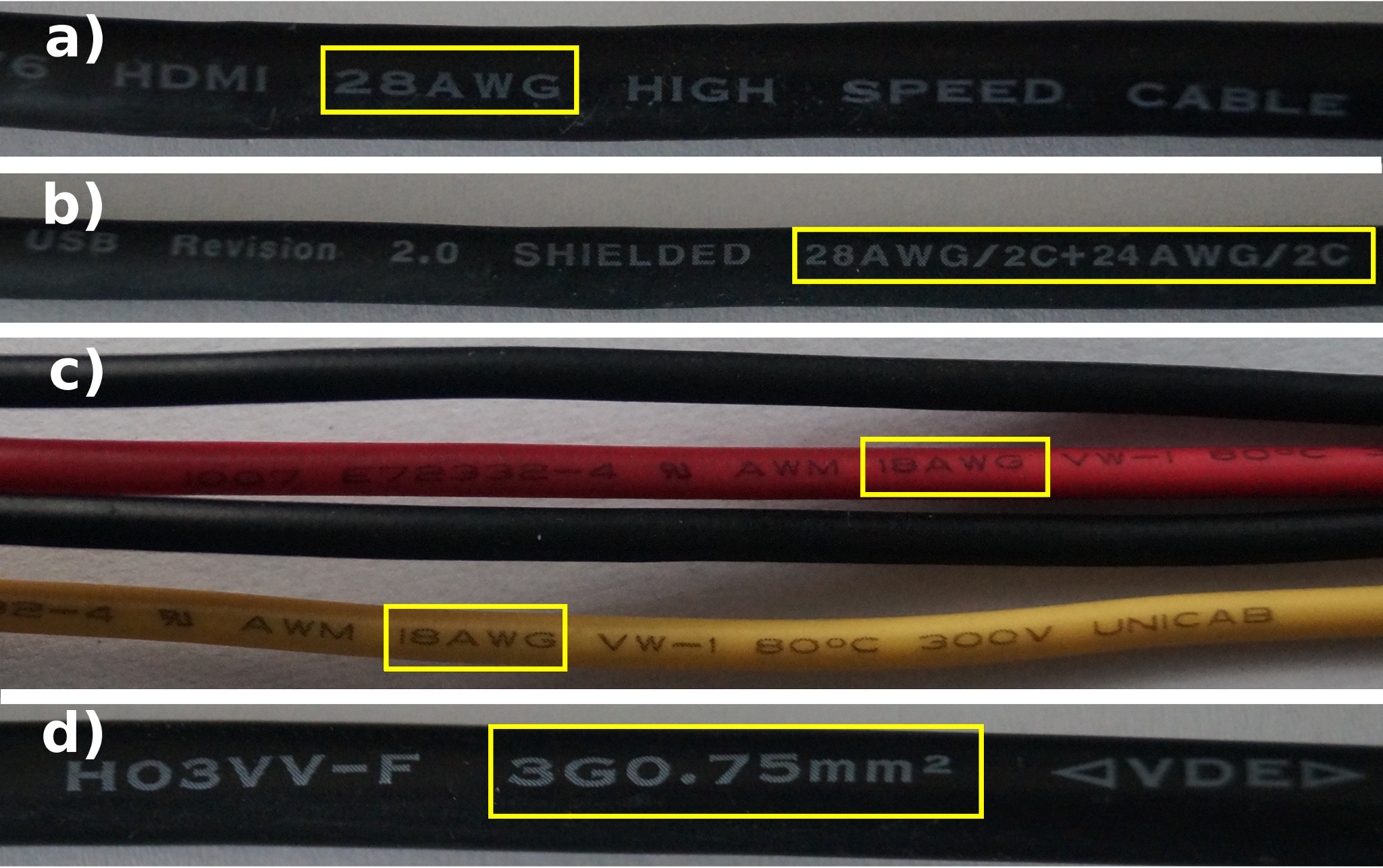
Fig. 4. Example wires manufactured to AWG and BS 6722:1986 include (a) HDMI, (b) USB, (c) 5 V and 12 V cables from power supply to PC, (d) power supply cable with IEC-C5 connector
The technical specifications included in the standards for data transmission or power supply interfaces include strict guidelines for manufacturing compatible cables. Considering that a majority of new technologies is still being developed in the USA (or in close cooperation with US companies), the wires used in electronic devices are mainly manufactured to AWG standards.
The computer networks use UTP and FTP cables, with a single strand diameter between No. 22 AWG and No. 24 AWG. For short sections, patch cords with No. 26 AWG strands can be used.
For HDMI – HDMI Working Group interface (developer of the standard) it is recommended that Standard HDMI Cable are made of No. 28 AWG strands, High Speed HDMI Cable are made of No. 24 AWG strands. The guidelines are not specified for Premium High Speed HDMI Cable.
In practice, AWG size depends on the cable length: – cables up to 3 m long require No. 30–28 AWG gauges, – cables 3 m to 10 m long require No. 28–26 AWG gauges, – cables over 10 m long – No. 26 AWG or lower gauges.
When connecting the devices transmitting a high volume of data (e.g. BluRay 3D or high-end graphics cards) to the receivers using 4K or higher resolution, it is recommended to use the shortest cables with the lowest AWG size possible.
For USB standard, two cable types are manufactured: – for data transmission between external devices (digital cameras, storage devices with external power supply etc.) and the PC – cables with a single size strands, usually No. 28 AWG; – for power supply – double AWG size marking (see Fig. 4b) – separate for D- and D+ (No. 28 AWG) and power supply and GND – usually No. 24 AWG.
As per the standard specification, power supply from USB should have a voltage of 5 V with ±5% (0.25 V) tolerance. USB supplied device (keyboard, portable HDD, internet camera etc.) should continue to operate at voltage drop between 0.55 V and 4.45 V (for USB 2.0) or between 0.6 V to 4.4 V (for USB 3.0).
The following tables (Table 3a–3d) show 5V voltage drop depending on strand diameter and wire length. The tables below show currents for the most popular USB chargers for mobile and portable devices: Table 3a - older phones; Table 3b, Table 3c and Table 3d – smartphones, tablets etc.
Table 3a. Power supply – 500 mA
AWG
15 cm
50 cm
1 m
2 m
3 m
5 m
20
0.064
0.076
0.093
0.126
0.159
0.226
22
0.067
0.086
0.112
0.165
0.218
0.324
24
0.072
0.102
0.144
0.228
0.312
0.481
26
0.080
0.126
0.193
0.327
0.461
0.729
28
0.091
0.166
0.272
0.485
0.698
1.124
Table 3b. Power supply – 1000 mA
AWG
15 cm
50 cm
1 m
2 m
3 m
5 m
20
0.129
0.153
0.186
0.253
0.319
0.453
22
0.125
0.172
0.225
0.331
0.437
0.649
24
0.145
0.204
0.288
0.456
0.625
0.962
26
0.160
0.253
0.387
0.655
0.923
1.459
28
0.183
0.332
0.545
0.971
1.397
2.249
Table 3c. Power supply – 2000 mA
AWG
15 cm
50 cm
1 m
2 m
3 m
5 m
20
0.259
0.306
0.373
0.506
0.639
0.906
22
0.271
0.345
0.451
0.663
0.875
1.299
24
0.290
0.408
0.576
0.913
1.250
1.924
26
0.320
0.507
0.775
1.311
1.846
2.918
28
0.367
0.665
1.091
1.943
2.794
4.498
Table 3d. Power supply – 2400 mA
AWG
15 cm
50 cm
1 m
2 m
3 m
5 m
20
0.311
0.367
0.447
0.607
0.767
1.087
22
0.326
0.415
0.542
0.796
1.050
1.559
24
0.348
0.490
0.692
1.096
1.500
2.309
26
0.384
0.609
0.930
1.573
2.216
3.501
28
0.412
0.798
1.309
2.331
3.353
5.397
The colours indicate supply voltage drop:
Green
- supply voltage drop up to 4.75 V
Yellow
- 4.75 V to 4.45 V
Yellow-red
- 4.45 V to 4.4 V
Red
- below 4.4 V
The values were calculated based on the Ohm’s law, allowing for the copper conductor and USB port resistance (approx. 30 mΩ).
The combinations of AWG size and cable length conforming to the voltage standard specification at the power supply cable output are marked green.
The combinations of AWG size and cable length for charge a smartphone are marked yellow (yellow-red for USB 3.0). The voltage drops below the voltage specified in the USB specification for charging devices (for a charger), and is maintained within the limits required for charged devices (e.g. tablet).
The cables that should not be used to charge USB devices with a specific charger are marked red.
It is worth noting that the cables with higher AWG size made from higher quality materials (non-doped, non-contaminated copper) and with better connectors will generate lower losses than those with higher thickness strands and doped e.g. with aluminium.
Electric cables that has been used in Europe for many years are manufactured to the metric standard BS 6722:1986. 1.5 mm2 and 2.5 mm2 diameter wires with permissible ampacity of 10 A and 16 A are most commonly used in the construction industry. In the countries using AWG system, No. 14 AWG (2.08 mm2) and No. 12 AWG (3.31 mm2) with maximum ampacity of 15 A and 20 A are concealed in the walls.
Net:
0.00
EUR
Gross:
0.00
EUR
Weight:
0.00
kg
This site uses cookies. More information about using by us cookie files, their usage and how to modify the acceptance of cookie files, can be found by pressing
link
 English
 Български
 Český
Český Dansk
Dansk Deutsch
 Eesti
Eesti Ελληνικά
 Español
 Français
 Italiano
 Latviešu
  Lietuvių
  Magyar
 Nederlands
 Polski
 Português
 Pусский
 Română
 Slovenski
 Slovenský
 Suomi
Suomi Svenska
 EUR
EUR AUD
AUD CAD
CAD CHF
CHF CZK
CZK DKK
DKK GBP
GBP HUF
HUF NOK
NOK PLN
PLN SEK
SEK USD
USD
 Home
Home Contact
 New products