Wave impedance is one of many parameters of coaxial cables. It is a type of electric resistance expressed in Ω (Ohm). The impedance is a complex quantity and defines the ratio of voltage to current in any location within the cable without any reflections for a properly connected cable. It means that the wave impedance of the cable should be equal to the output impedance of the transmitter and the input impedance of the receiver. The cable should be matched with a connector of the same impedance.
Coaxial cables are available in different wave impedances for different applications. Properties of cables with the most common impedances (75 Ω and 50 Ω) are shown below. All other cables are usually intended for special applications (e.g. measuring instruments probes) and are relatively uncommon.
75 Ω coaxial cables are used in TV and CCTV applications, usually as antenna cables for TV broadcast systems. Popular 75 Ω coaxial cables RG-6/U or TRISET-113 are available in Delta offer.
50 Ω coaxial cables are used in radio communication (e.g. CB radio) or radio waves data transmission (e.g. WLAN 2.4 GHz). 50 Ω coaxial cables have been previously used in the computer networks, however, those have been replaced by UTP and FTP, commonly referred to as twisted pair cables. TRI-LAN-240 available in Delta offer is an example 50 Ω coaxial cable.
Cable impedance depends on the internal core diameter, external cable diameter and permittivity of the insulation. In accordance with the general standards, the cable diameters must have specific dimensions and the required cable impedance can be achieved using a dielectric with a required permittivity, e.g. by expanding its structure or using a dielectric made of different materials.
As mentioned previously, it is also critical to use compatible connectors for the coaxial cables, e.g. BNC connectors or plugs that also have 50 Ω or 75 Ω impedance. It prevents wave reflection within the cable and thus signal distortions.
Let’s discuss impedance measurements
You must admit that ‘impedance’ has some mysterious connotations.
The manufacturers of coaxial cables specify the technical parameters for their products in the data sheets. For example: ‘Cable impedance: 50 (or 75) Ohm’. My inherent scepticism towards publicly available information tells me to verify the reliability of this statement. There, the problem arises - how to measure wave impedance of a cable? And what if we have to deal with an unmarked coil of a coaxial cable? Is it 50 or 75 Ohm?
I suggest a quick test. Whoever chooses an instrument that can be used to measure wave impedance of a cable within the next 60 seconds wins!
1. Ohmmeter 2. Wavemeter 3. Waveguide 4. Breakwater 5. Cable meter 3. Wall cable detector 7. Wheatstone bridge 8. Exhaust gas analyser 9. Measuring tape 10. Complex number meter 11. Variometer 12. Slide caliper 13. Analytical balance 14. Pseudo number generator 15. Digital slide rule
The test was a tricky one, so by any means do not feel bad if you have failed, but keep reading.
The instrument we can use a simple slide caliper.
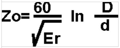
Using a core diameter and an inside shield diameter we can calculate the wave impedance of a cable using the following equation:
Zo - cable impedance [Ohm]
D - shield diameter [mm]
d - core diameter [mm]
Er - dielectric permittivity [abstract unit]
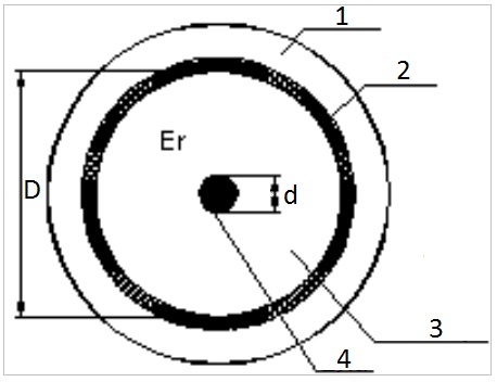
The diagram will make everything clear:
1 - cover
2 - shield
3 - dielectric
4 - wire
Well, maybe not the cable’s permittivity coefficient Er. The coefficient depends on the type of dielectric used. For air Er=1, for solid polyethylene Er=2.3. For expanded polyethylene, Er depends on the degree of expansion and shape of the air cells. Without going into too much detail, Er for the expanded polyethylene is 1.5. Even if it differs slightly (due to PE to air ratio), the result can be: either 50 or 75 Ohm, and the error will be insignificant. With some practice, the cable impedance can be correctly determined visually. The thicker core is usually 50 Ohm, the thinner is 75 Ohm.
When the fuse blows, we repair it with a section of a thick wire and we are good to go. The conclusion seems obvious: The thicker the wire, the higher the current flow and thus less problems with power supply. Can the same conclusion be applied to the cable impedance? Is it better or worse if the cable impedance is high? Does the lower impedance means increased current flow?
Why are there no coaxial cables available in impedances other than 50 or 75 Ohm, e.g. every 5 Ohm (although, 60 Ohm cables were available in the past).
And the last question: Why 50 Ohm and not 140 or 30? Anyone who will answer the last question correctly will be awarded a platinum certificate for the Technical Engineer of the Year issued by DELTA-OPTI. I’ve also recently noticed, that regardless of our understanding of the term ‘impedance’, using it in writing and speech will increase our social standing and gain us respect.
Net:
0.00
EUR
Gross:
0.00
EUR
Weight:
0.00
kg
This site uses cookies. More information about using by us cookie files, their usage and how to modify the acceptance of cookie files, can be found by pressing
link
 English
 Български
 Český
Český Dansk
Dansk Deutsch
 Eesti
Eesti Ελληνικά
 Español
 Français
 Italiano
 Latviešu
  Lietuvių
  Magyar
 Nederlands
 Polski
 Português
 Pусский
 Română
 Slovenski
 Slovenský
 Suomi
Suomi Svenska
 EUR
EUR AUD
AUD CAD
CAD CHF
CHF CZK
CZK DKK
DKK GBP
GBP HUF
HUF NOK
NOK PLN
PLN SEK
SEK USD
USD
 Home
Home Contact
 New products