Switched mode power supplies - protectionsThe designers of power supplies use different methods to prevent short circuits and overloads. The protection should guarantee safety of both the power supply and the load. The most commonly used protections are discussed below.
|
It is one of the most commonly used protections hiccup characterised by low power loss in the power supply due to overload or short circuit and automatic restoration of normal operation after the cause of the short circuit or overload has been eliminated.
|
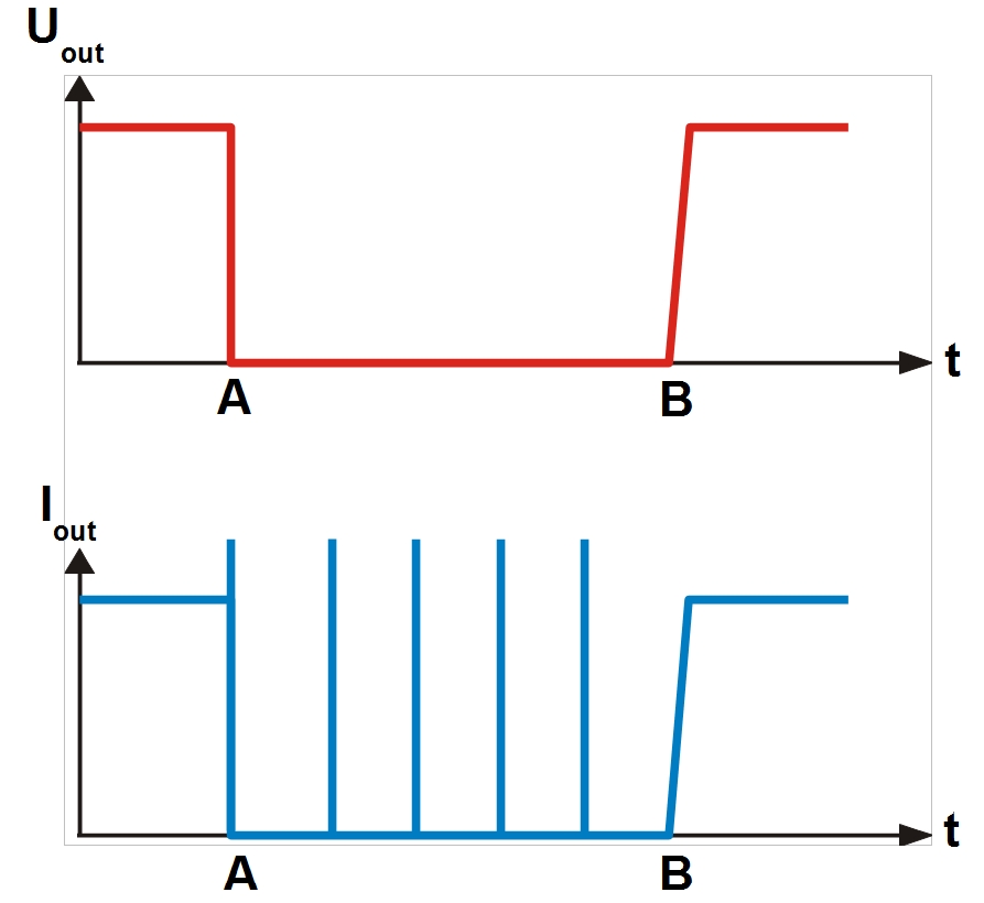
The diagram below shows the basic working principle of hiccup type protection. | 
| Uout - output voltage Iout - output current t - time A – short-circuit (overload) B – short-circuit cause eliminated |
|
Overload or short-circuit take place at A. Power supply is disconnected. Very short duration current pulse (e.g. 100 ms) at 150% maximum current is generated at the output. The power supply will transmit this pulse every several seconds until the cause for overload or short-circuit (B) is eliminated and restores normal operation mode. In most cases, the activation threshold (power supply disconnection) is set to 110 to 150% rated current (Iout). This mode is usually integrated with a thermal protection. If the load requires current higher than the rated current but lower than the threshold, the thermal protection will be activated after a while to disconnect the power supply and switch to hiccup mode until the cause for the overload is eliminated.
|
Other types of protections against high current input are shown below (3 curves: A, B and C). | 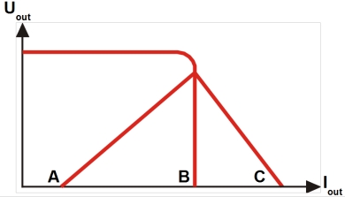
| Uout - output voltage Iout - output current |
|
Curve A – foldback current limiting (Foldback Current Limiting)
This type of protection is also used in linear power supplies. After the maximum current is exceeded (reduced load resistance), the current is reduced. In other words, if the load resistance is reduced the current is also reduced. This method is characterized by low power loss at the power supply in case of an overload or short-circuit. However, the power supply will not start with loads that require high starting currents (e.g. high capacity loads).
|
Curve B – constant current limiting (Constant Current Limiting)
After exceeding the maximum current (reduced load resistance), the power supply maintains constant output current regardless of the overload simultaneously reducing the output voltage. Auxiliary protection disconnecting the power supply in case the voltage drops to several volts is often used. This method is characterized by large power losses at the power supply and high current flow through the load that may result in damage. This type of protection allows to start a power supply with non-linear loads connected.
|
Curve C – overpower limiting (Over Power Limiting)
After the maximum current is exceeded (reduced load resistance), the output power of the power supply is maintained at a constant level. With the increase in load, the voltage and the output current drop in accordance with the C curve. This type of protection allows to start a power supply with non-linear loads connected.
|
|