AWGAWG (American Wire Gauge) – is an American standardized system for determining diameters or cross-sectional areas of wires.
|
AWG is expressed as integer value (e.g. 1, 2 or 15) corresponding to a specific dimension (in mm, inches, mm2 or kcmil). Within this system, increasing gauge numbers denote decreasing wire size.
Example: 1 AWG = 42.40 mm2, whereas 28 AWG = 0.32 mm2.
|
Fig. 1. Approximate ratio (in a suitable scale) of different wire sizes in AWG standard 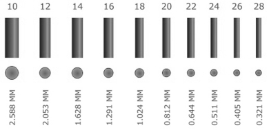
|
AWG standard has been developed at the beginning of the 19th century, with its final version developed in 1957 by Joseph Rogers Brown for Browne & Sharpe - a manufacturer of measuring instruments. AWG is also called Brown and Sharpe wire gauge (B&S).
The inverse order of the AWG is due to the wire production process used at the time the system has been developed. At first, AWG corresponded to the number of drawing operations used to produce a given gauge of wire on the drawing die. A blank with a 160 kcmil cross-sectional area requires 20 drawing operations through successively smaller dies to reach the desired size - a wire with a 1.02 kcmil (20 AWG) cross-sectional area. The gauges below one (0 [1/0], 00 [2/0], 000 [3/0] and 0000 [4/0]) has been introduced at a later date, and the wires with corresponding dimensions were manufactured from blanks, compacts or cast rods with cross-sectional area over 106 kcmil.
|
Fig. 2. Changes in gauge number after a single draw of the wire through each die: (a) initial wire, (b) to (d) subsequent gauge wires. Example: (a) = 6 AWG → (e) = 10 AWG 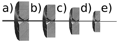
|
There are 44 gauge sizes: from No. 0000 [4/0] corresponding to the largest wire diameter to No. 40 corresponding to the smallest wire diameter. Each successive gauge number increases cross-sectional area by approx. 20.5% and diameter by approx. 10.25%. The drawing dies used by Brown & Sharpe allowed to reduce the wire diameter by exactly 10.25%.
It leads to the following:
– when the cross-sectional area is doubled, the gauge will decrease by 3, e.g. two No. 12 AWG has the same cross-sectional area as a single No. 9 AWG wire;
– when the diameter of a wire is doubled, the gauge will decrease by 6, e.g. No. 9 AWG wire is about twice the diameter of No. 15 AWG wire;
– when the diameter of a wire is tripled, the gauge will decrease by 10;
– when the diameter of a wire is increased fivefold, the gauge will decrease by 14;
– when the diameter of a wire is increased tenfold, the gauge will decrease by 20.
Physical properties of the wire materials also impose certain rules. Aluminium wire has a conductivity of approx. 61% of copper. The aluminium wires has the same resistance as a copper wire smaller by 2 AWG sizes.
|
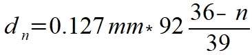
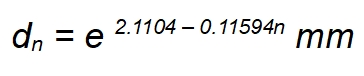
An accurate wire diameter (in mm) for a specific AWG size may be expressed as follows: 
|
and 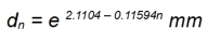
|
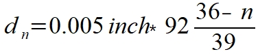
or in inches: 
|
and 
|
where:
d – diameter,
n – AWG size.
|
Table 1 shows dimensions and basic physical properties of the various wire gauges.
|
Table 1. American Wire Gauge (AWG) – dimensions, resistances and maximum ampacity (DC) and a maximum frequency at which the skin effect does not occur (AC). All parameters are based on a copper wire at 25°C | AWG | Diameter | Cross-sectional area | Resistance | Maximum ampacity as: | Maximum frequency for skin depth = 100% area | | mm | inch | mm² | kcmil | Ω/km | Ω/kft | GND [A] | power supply [A] | | 0000
[4/0] | 11.684 | 0.4600 | 107 | 212 | 0.1608 | 0.04901 | 380 | 302 | 125 Hz | 000
[3/0] | 10.404 | 0.4096 | 85 | 168 | 0.2028 | 0.06180 | 328 | 239 | 160 Hz | 00
[2/0] | 9.266 | 0.3648 | 67.4 | 133 | 0.2557 | 0.07793 | 283 | 190 | 200 Hz | 0
[1/0] | 8.252 | 0.3249 | 53.5 | 106 | 0.3224 | 0.09827 | 245 | 150 | 250 Hz | | 1 | 7.348 | 0.2893 | 42.4 | 83.7 | 0.4066 | 0.1239 | 211 | 119 | 325 Hz | | 2 | 6.544 | 0.2576 | 33.6 | 66.4 | 0.5127 | 0.1563 | 181 | 94 | 410 Hz | | 3 | 5.827 | 0.2294 | 26.7 | 52.6 | 0.6465 | 0.1970 | 158 | 75 | 500 Hz | | 4 | 5.189 | 0.2043 | 21.2 | 41.7 | 0.8152 | 0.2485 | 135 | 60 | 650 Hz | | 5 | 4.621 | 0.1819 | 16.8 | 33.1 | 1.028 | 0.3133 | 118 | 47 | 810 Hz | | 6 | 4.115 | 0.1620 | 13.3 | 26.3 | 1.296 | 0.3951 | 101 | 37 | 1100 Hz | | 7 | 3.665 | 0.1443 | 10.5 | 20.8 | 1.634 | 0.4982 | 89 | 30 | 1300 Hz | | 8 | 3.264 | 0.1285 | 8.37 | 16.5 | 2.061 | 0.6282 | 73 | 24 | 1650 Hz | | 9 | 2.906 | 0.1144 | 6.63 | 13.1 | 2.599 | 0.7921 | 64 | 19 | 2050 Hz | | 10 | 2.588 | 0.1019 | 5.26 | 10.4 | 3.277 | 0.9989 | 55 | 15 | 2600 Hz | | 11 | 2.305 | 0.0907 | 4.17 | 8.23 | 4.132 | 1.260 | 47 | 12 | 3200 Hz | | 12 | 2.053 | 0.0808 | 3.31 | 6.53 | 5.211 | 1.588 | 41 | 9.3 | 4150 Hz | | 13 | 1.828 | 0.0720 | 2.62 | 5.18 | 6.571 | 2.003 | 35 | 7.4 | 5300 Hz | | 14 | 1.628 | 0.0641 | 2.08 | 4.11 | 8.286 | 2.525 | 32 | 5.9 | 6700 Hz | | 15 | 1.450 | 0.0571 | 1.65 | 3.26 | 10.45 | 3.184 | 28 | 4.7 | 8250 Hz | | 16 | 1.291 | 0.0508 | 1.31 | 2.58 | 13.17 | 4.016 | 22 | 3.7 | 11 kHz | | 17 | 1.150 | 0.0453 | 1.04 | 2.05 | 16.61 | 5.064 | 19 | 2.9 | 13 kHz | | 18 | 1.024 | 0.0403 | 0.823 | 1.62 | 20.95 | 6.385 | 16 | 2.3 | 17 kHz | | 19 | 0.912 | 0.0359 | 0.653 | 1.29 | 26.42 | 8.051 | 14 | 1.8 | 21 kHz | | 20 | 0.812 | 0.0320 | 0.518 | 1.02 | 33.31 | 10.15 | 11 | 1.5 | 27 kHz | | 21 | 0.723 | 0.0285 | 0.410 | 0.810 | 42.00 | 12.80 | 9 | 1.2 | 33 kHz | | 22 | 0.643 | 0.0253 | 0.326 | 0.642 | 52.96 | 16.14 | 7 | 0.92 | 42 kHz | | 23 | 0.573 | 0.0226 | 0.258 | 0.509 | 66.79 | 20.36 | 4.7 | 0.73 | 53 kHz | | 24 | 0.511 | 0.0201 | 0.205 | 0.404 | 84.22 | 25.67 | 3.5 | 0.58 | 68 kHz | | 25 | 0.455 | 0.0179 | 0.162 | 0.320 | 106.2 | 32.37 | 2.7 | 0.46 | 85 kHz | | 26 | 0.405 | 0.0159 | 0.129 | 0.254 | 133.9 | 40.81 | 2.2 | 0.36 | 107 kHz | | 27 | 0.361 | 0.0142 | 0.102 | 0.202 | 168.9 | 51.47 | 1.7 | 0.29 | 130 kHz | | 28 | 0.321 | 0.0126 | 0.0810 | 0.160 | 212.9 | 64.9 | 1.4 | 0.23 | 170 kHz | | 29 | 0.286 | 0.0113 | 0.0642 | 0.127 | 268.5 | 81.84 | 1.2 | 0.18 | 210 kHz | | 30 | 0.255 | 0.0100 | 0.0509 | 0.101 | 338.6 | 103.2 | 0.86 | 0.14 | 270 kHz | | 31 | 0.227 | 0.00893 | 0.0404 | 0.0797 | 426.9 | 130.1 | 0.70 | 0.11 | 340 kHz | | 32 | 0.202 | 0.00795 | 0.0320 | 0.0632 | 538.3 | 164.1 | 0.53 | 0.09 | 430 kHz | | 33 | 0.180 | 0.00708 | 0.0254 | 0.0501 | 678.8 | 206.9 | 0.43 | 0.07 | 540 kHz | | 34 | 0.160 | 0.00630 | 0.0201 | 0.0398 | 856.0 | 260.9 | 0.33 | 0.06 | 690 kHz | | 35 | 0.143 | 0.00561 | 0.0160 | 0.0315 | 1079 | 329.0 | 0.27 | 0.04 | 870 kHz | | 36 | 0.127 | 0.00500 | 0.0127 | 0.0250 | 1361 | 414.8 | 0.21 | 0.04 | 1100 kHz | | 37 | 0.113 | 0.00445 | 0.0100 | 0.0198 | 1716 | 523.1 | 0.17 | 0.03 | 1350 kHz | | 38 | 0.101 | 0.00397 | 0.00797 | 0.0157 | 2164 | 659.6 | 0.13 | 0.02 | 1750 kHz | | 39 | 0.0897 | 0.00353 | 0.00632 | 0.0125 | 2729 | 831.8 | 0.11 | 0.02 | 2250 kHz | | 40 | 0.0799 | 0.00314 | 0.00501 | 0.00989 | 3441 | 1049 | 0.09 | 0.01 | 2900 kHz |
|
Diameters of solid wires and stranded wires of the same AWG size are different, since the diameter/cross-sectional area determines the AWG wire size. Cross-sectional area/diameter of the stranded wire includes wires and gaps between the wires. The gaps depend on the wire layout within the round stranded wire. The AWG gauge of a stranded wire represents the sum of the cross-sectional areas of the individual wires, and not the cross-sectional area of the stranded wire as a whole.
Table 2 shows parameters of a solid wire and a stranded wire. Layout, outer diameter and cross-sectional area (including gaps between wires – not including insulation) and wire resistance (in Ω/km) are compared.
|
Table 2. Comparison of basic parameters of solid wires and stranded wires (n – number of wires) | AWG | Wire layout | Diameter | Cross-sectional area | Resistance | | n/AWG | n x mm | mm | mm² | Ω/km | 0000
[4/0] | Single solid wire | 11.684 | 107 | 0.16 | | 259/21 | 259 x 0.724 | 13.259 | 106.63 | 0.16 | | 427/23 | 427 x 0.574 | 13.259 | 110.49 | 0.15 | 000
[3/0] | Single solid wire | 10.405 | 85.0 | 0.20 | | 259/22 | 259 x 0.643 | 11.786 | 84.40 | 0.20 | | 427/24 | 427 x 0.511 | 11.786 | 87.57 | 0.19 | 00
[2/0] | Single solid wire | 9.266 | 67.4 | 0.25 | | 133/20 | 133 x 0.813 | 10.516 | 69.04 | 0.25 | | 259/23 | 259 x 0.574 | 10.516 | 67.02 | 0.25 | 0
[1/0] | Single solid wire | 8.251 | 53.5 | 0.32 | | 133/21 | 133 x 0.724 | 9.347 | 54.75 | 0.31 | | 259/24 | 259 x 0.511 | 9.347 | 53.12 | 0.32 | | 1 | Single solid wire | 7.348 | 42.4 | 0.40 | | 133/22 | 133 x 0.643 | 8.331 | 43.19 | 0.40 | | 259/25 | 259 x 0.045 | 8.331 | 42.11 | 0.41 | | 817/30 | 817 x 0.254 | 8.331 | 41.40 | 0.42 | | 2109/36 | 2109 x 0.160 | 8.331 | 42.40 | 0.41 | | 2 | Single solid wire | 6.544 | 33.60 | 0.51 | | 133/23 | 133 x 0.574 | 7.417 | 34.42 | 0.50 | | 259/26 | 259 x 0.404 | 7.417 | 33.20 | 0.52 | | 665/30 | 665 x 0.256 | 7.417 | 33.70 | 0.52 | | 2646/36 | 2646 x 0.127 | 7.417 | 33.52 | 0.52 | | 4 | Single solid wire | 5.189 | 21.20 | 0.82 | | 133/225 | 133 x 0.455 | 5.898 | 21.63 | 0.80 | | 259/27 | 259 x 0.363 | 5.898 | 26.80 | 0.66 | | 1666/36 | 1666 x 0.127 | 5.898 | 21.10 | 0.82 | | 6 | Single solid wire | 4.115 | 13.30 | 1.29 | | 133/27 | 133 x 0.363 | 4.674 | 13.76 | 1.50 | | 259/30 | 259 x 0.254 | 4.674 | 13.12 | 1.30 | | 1050/36 | 1050 x 0.127 | 4.674 | 13.32 | 1.30 | | 8 | Single solid wire | 3.264 | 8.37 | 2.06 | | 49/25 | 49 x 0.455 | 3.734 | 7.96 | 2.20 | | 133/29 | 133 x 0.287 | 3.734 | 8.60 | 2.00 | | 655/36 | 655 x 0.127 | 3.734 | 8.30 | 2.00 | | 10 | Single solid wire | 2.588 | 5.26 | 3.27 | | 37/26 | 37 x 0.404 | 2.921 | 4.74 | 3.60 | | 49/27 | 49 x 0.363 | 2.946 | 5.07 | 3.60 | | 105/30 | 105 x 0.254 | 2.946 | 5.32 | 3.20 | | 12 | Single solid wire | 2.053 | 3.21 | 5.21 | | 7/20 | 7 x 0.813 | 2.438 | 3.63 | 4.80 | | 19/25 | 19 x 0.455 | 2.369 | 3.09 | 5.60 | | 65/30 | 65 x 0.254 | 2.413 | 3.29 | 5.70 | | 165/34 | 165 x 0.160 | 2.413 | 3.32 | 5.20 | | 14 | Single solid wire | 1.628 | 2.08 | 8.28 | | 7/22 | 7 x 0.643 | 1.854 | 2.238 | 7.60 | | 19/27 | 19 x 0.361 | 1.854 | 1.945 | 8.90 | | 41/30 | 41 x 0.254 | 1.854 | 2.078 | 8.30 | | 105/34 | 105 x 0.160 | 1.854 | 2.111 | 8.20 | | 16 | Single solid wire | 1.291 | 1.310 | 13.2 | | 7/24 | 7 x 0.511 | 1.524 | 1.440 | 12.0 | | 19/29 | 19 x 0.287 | 1.473 | 1.229 | 14.0 | | 26/30 | 26 x 0.254 | 1.499 | 1.317 | 13.1 | | 65/34 | 65 x 0.160 | 1.499 | 1.310 | 13.2 | | 105/36 | 105 x 0.127 | 1.499 | 1.330 | 13.1 | | 18 | Single solid wire | 1.024 | 0.823 | 21.0 | | 7/26 | 7 x 0.404 | 1.219 | 0.897 | 19.2 | | 16/30 | 16 x 0.254 | 1.194 | 0.811 | 21.3 | | 19/30 | 19 x 0.254 | 1.245 | 0.963 | 17.9 | | 41/34 | 41 x 0.160 | 1.194 | 0.824 | 20.9 | | 65/36 | 65 x 0.127 | 1.194 | 0.823 | 21.0 | | 20 | Single solid wire | 0.812 | 0.518 | 33.3 | | 7/28 | 7 x 0.320 | 0.865 | 0.562 | 33.8 | | 10/30 | 10 x 0.254 | 0.889 | 0.507 | 33.9 | | 19/32 | 19 x 0.203 | 0.940 | 0.615 | 28.3 | | 26/34 | 26 x 0.160 | 0.914 | 0.523 | 33.0 | | 41/36 | 41 x 0.127 | 0.914 | 0.520 | 32.9 | | 22 | Single solid wire | 0.644 | 0.326 | 53.0 | | 7/30 | 7 x 0.254 | 0.762 | 0.355 | 48.4 | | 19/34 | 19 x 0.160 | 0.787 | 0.382 | 45.1 | | 26/36 | 26 x 0.127 | 0.762 | 0.330 | 52.3 | | 24 | Single solid wire | 0.511 | 0.205 | 84.2 | | 7/32 | 7 x 0.203 | 0.610 | 0.227 | 76.4 | | 10/34 | 10 x 0.160 | 0.582 | 0.201 | 85.6 | | 19/36 | 19 x 0.127 | 0.610 | 0.241 | 69.2 | | 41/40 | 41 x 0.078 | 0.582 | 0.196 | 84.0 | | 26 | Single solid wire | 0.405 | 0.129 | 133.9 | | 7/34 | 7 x 0.160 | 0.483 | 0.141 | 122.0 | | 19/38 | 19 x 0.102 | 0.508 | 0.155 | 113.0 | | 10/36 | 10 x 0.127 | 0.533 | 0.127 | 137.0 | | 28 | Single solid wire | 0.321 | 0.081 | 212.9 | | 7/36 | 7 x 0.127 | 0.381 | 0.087 | 213.0 | | 19/40 | 19 x 0.078 | 0.406 | 0.091 | 186.0 | | 30 | Single solid wire | 0.255 | 0.050 | 338.6 | | 7/38 | 7 x 0.102 | 0.305 | 0.057 | 339.0 | | 19/42 | 19 x 0.064 | 0.305 | 0.061 | 286.7 | | 32 | Single solid wire | 0.202 | 0.032 | 538.3 | | 7/40 | 7 x 0.078 | 0.203 | 0.034 | 538.0 | | 19/44 | 19 x 0.050 | 0.229 | 0.037 | 448.0 | | 34 | Single solid wire | 0.160 | 0.020 | 856.0 | | 7/42 | 7 x 0.064 | 0.192 | 0.022 | 777.0 | | 36 | Single solid wire | 0.127 | 0.013 | 1362.0 | | 7/44 | 7 x 0.050 | 0.152 | 0.014 | 1271.0 |
|
The table shows a list of AWG sizes from 4/0 [No. 0000] to No. 2 and successive even AWG sizes up to No. 36 incl. Wires with AWG size over 36 are not available as stranded wires, since the wire diameter required would have to be extremely small.
|
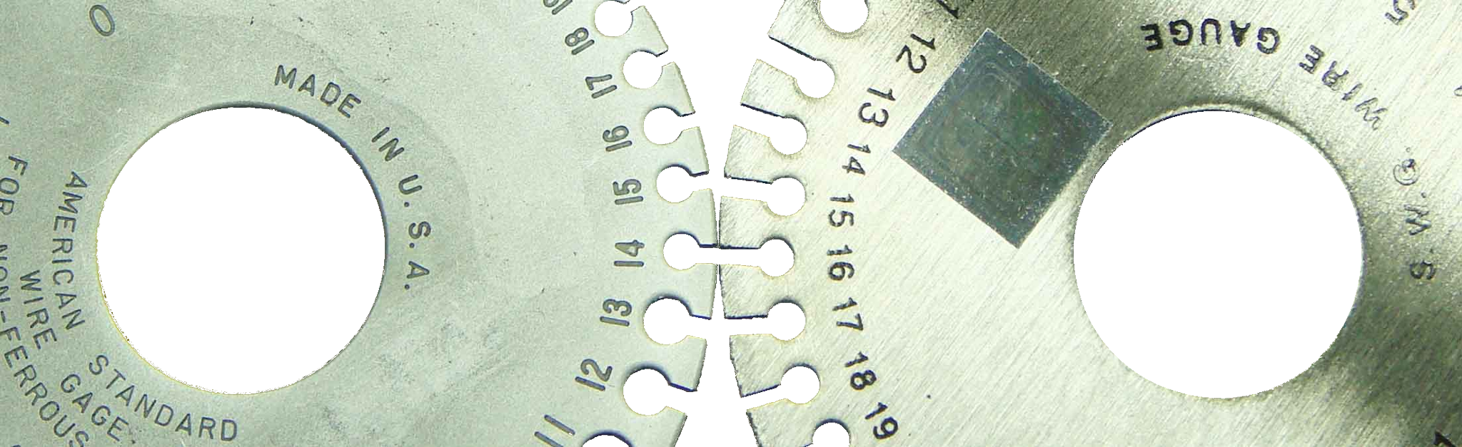
AWG has been developed and initially used in the USA. It is now widely used worldwide, replacing other systems and standards. It has competed with a British Birmingham Wire Gauge (BWG) system, however, at the end of the 19th century, slightly modified BWG has been replaced by Standard Wire Gauge (SWG), now widely used in the UK. SWG is also known as Imperial Wire Gauge or British Standard Gauge. SWG gauges look almost identical to AWG gauges, however the sizes correspond to different wire dimensions.
|
Fig. 3. Comparison of AWG (left) and SWG (right) wire gauges. No. 14 AWG ≈ No. 16 SWG 
|
Fig. 3 shows No. 14 AWG as nearly equal to No. 16 SWG.
The main difference between AWG and SWG is the material of the wire. The American system has been developed to measure solid and stranded wires made of metals and non-ferrous alloys (non-magnetic) - mainly copper, but also aluminium or silver. The British standard has been developed to standardize the sizes of ferrous wires. There are 44 basic AWG gauge sizes and 57 SWG gauge sizes.
Standard Wire Gauge has been gradually withdrawn and replaced by BS 6722:1986.
|
AWG is commonly used in the manufacturing of different wire types in countries using the imperial system of measurements. In countries using the metric system, both BS 6722:1986 and AWG are used depending on the application of the manufactured wire.
|
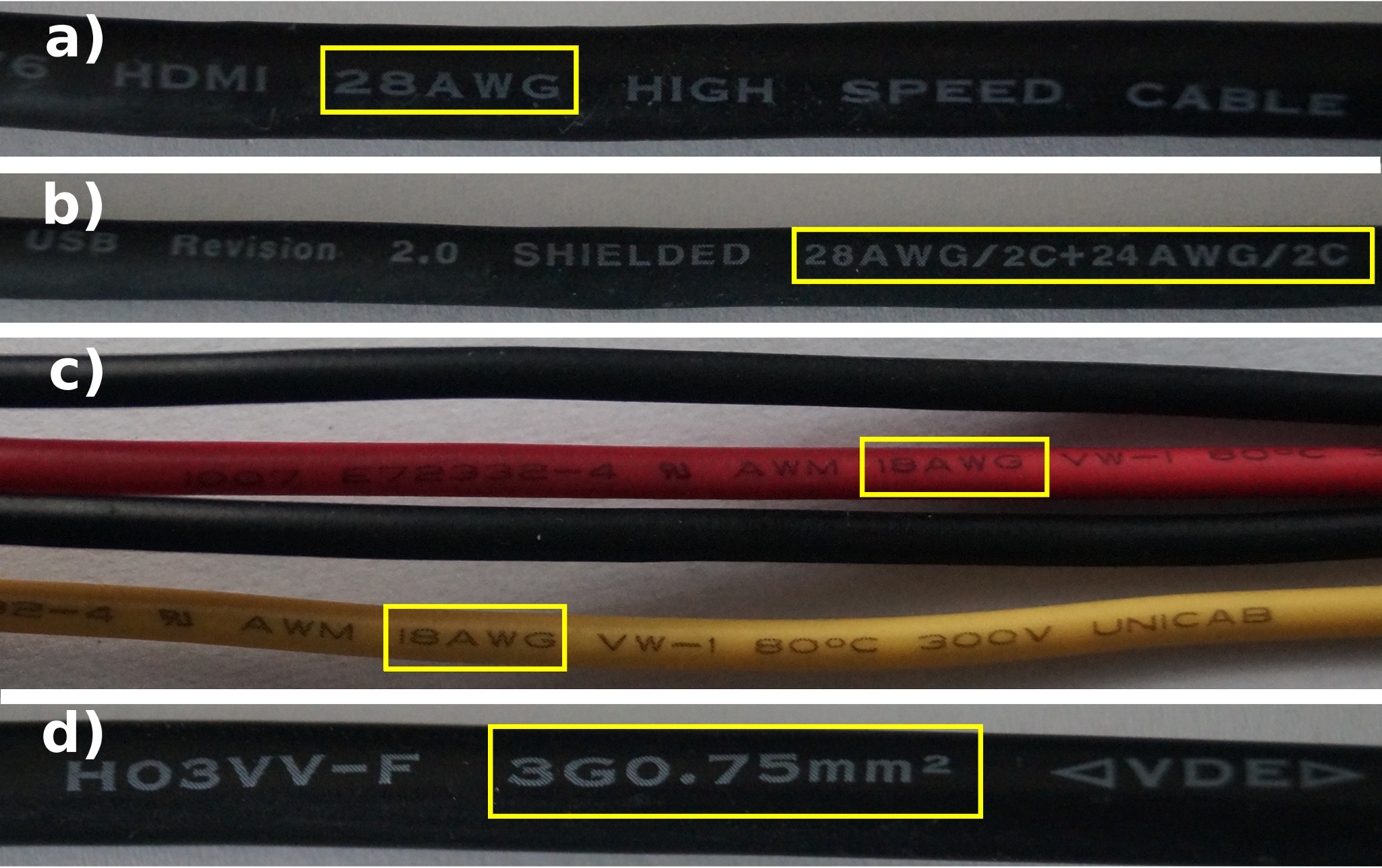
Fig. 4. Example wires manufactured to AWG and BS 6722:1986 include (a) HDMI, (b) USB, (c) 5 V and 12 V cables from power supply to PC, (d) power supply cable with IEC-C5 connector 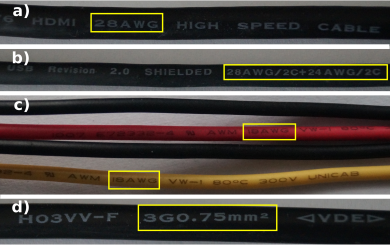
|
The technical specifications included in the standards for data transmission or power supply interfaces include strict guidelines for manufacturing compatible cables. Considering that a majority of new technologies is still being developed in the USA (or in close cooperation with US companies), the wires used in electronic devices are mainly manufactured to AWG standards.
The computer networks use UTP and FTP cables, with a single strand diameter between No. 22 AWG and No. 24 AWG. For short sections, patch cords with No. 26 AWG strands can be used.
For HDMI – HDMI Working Group interface (developer of the standard) it is recommended that Standard HDMI Cable are made of No. 28 AWG strands, High Speed HDMI Cable are made of No. 24 AWG strands. The guidelines are not specified for Premium High Speed HDMI Cable.
In practice, AWG size depends on the cable length:
– cables up to 3 m long require No. 30–28 AWG gauges,
– cables 3 m to 10 m long require No. 28–26 AWG gauges,
– cables over 10 m long – No. 26 AWG or lower gauges.
|
When connecting the devices transmitting a high volume of data (e.g. BluRay 3D or high-end graphics cards) to the receivers using 4K or higher resolution, it is recommended to use the shortest cables with the lowest AWG size possible.
|
For USB standard, two cable types are manufactured:
– for data transmission between external devices (digital cameras, storage devices with external power supply etc.) and the PC – cables with a single size strands, usually No. 28 AWG;
– for power supply – double AWG size marking (see Fig. 4b) – separate for D- and D+ (No. 28 AWG) and power supply and GND – usually No. 24 AWG.
|
As per the standard specification, power supply from USB should have a voltage of 5 V with ±5% (0.25 V) tolerance. USB supplied device (keyboard, portable HDD, internet camera etc.) should continue to operate at voltage drop between 0.55 V and 4.45 V (for USB 2.0) or between 0.6 V to 4.4 V (for USB 3.0).
|
The following tables (Table 3a–3d) show 5V voltage drop depending on strand diameter and wire length. The tables below show currents for the most popular USB chargers for mobile and portable devices: Table 3a - older phones; Table 3b, Table 3c and Table 3d – smartphones, tablets etc.
|
Table 3a. Power supply – 500 mA | AWG | 15 cm | 50 cm | 1 m | 2 m | 3 m | 5 m | | 20 | 0.064 | 0.076 | 0.093 | 0.126 | 0.159 | 0.226 | | 22 | 0.067 | 0.086 | 0.112 | 0.165 | 0.218 | 0.324 | | 24 | 0.072 | 0.102 | 0.144 | 0.228 | 0.312 | 0.481 | | 26 | 0.080 | 0.126 | 0.193 | 0.327 | 0.461 | 0.729 | | 28 | 0.091 | 0.166 | 0.272 | 0.485 | 0.698 | 1.124 |
|
Table 3b. Power supply – 1000 mA | AWG | 15 cm | 50 cm | 1 m | 2 m | 3 m | 5 m | | 20 | 0.129 | 0.153 | 0.186 | 0.253 | 0.319 | 0.453 | | 22 | 0.125 | 0.172 | 0.225 | 0.331 | 0.437 | 0.649 | | 24 | 0.145 | 0.204 | 0.288 | 0.456 | 0.625 | 0.962 | | 26 | 0.160 | 0.253 | 0.387 | 0.655 | 0.923 | 1.459 | | 28 | 0.183 | 0.332 | 0.545 | 0.971 | 1.397 | 2.249 |
|
Table 3c. Power supply – 2000 mA | AWG | 15 cm | 50 cm | 1 m | 2 m | 3 m | 5 m | | 20 | 0.259 | 0.306 | 0.373 | 0.506 | 0.639 | 0.906 | | 22 | 0.271 | 0.345 | 0.451 | 0.663 | 0.875 | 1.299 | | 24 | 0.290 | 0.408 | 0.576 | 0.913 | 1.250 | 1.924 | | 26 | 0.320 | 0.507 | 0.775 | 1.311 | 1.846 | 2.918 | | 28 | 0.367 | 0.665 | 1.091 | 1.943 | 2.794 | 4.498 |
|
Table 3d. Power supply – 2400 mA | AWG | 15 cm | 50 cm | 1 m | 2 m | 3 m | 5 m | | 20 | 0.311 | 0.367 | 0.447 | 0.607 | 0.767 | 1.087 | | 22 | 0.326 | 0.415 | 0.542 | 0.796 | 1.050 | 1.559 | | 24 | 0.348 | 0.490 | 0.692 | 1.096 | 1.500 | 2.309 | | 26 | 0.384 | 0.609 | 0.930 | 1.573 | 2.216 | 3.501 | | 28 | 0.412 | 0.798 | 1.309 | 2.331 | 3.353 | 5.397 |
|
The colours indicate supply voltage drop: | Green | - supply voltage drop up to 4.75 V | | Yellow | - 4.75 V to 4.45 V | | Yellow-red | - 4.45 V to 4.4 V | | Red | - below 4.4 V |
|
The values were calculated based on the Ohm’s law, allowing for the copper conductor and USB port resistance (approx. 30 mΩ).
The combinations of AWG size and cable length conforming to the voltage standard specification at the power supply cable output are marked green.
The combinations of AWG size and cable length for charge a smartphone are marked yellow (yellow-red for USB 3.0). The voltage drops below the voltage specified in the USB specification for charging devices (for a charger), and is maintained within the limits required for charged devices (e.g. tablet).
The cables that should not be used to charge USB devices with a specific charger are marked red.
|
It is worth noting that the cables with higher AWG size made from higher quality materials (non-doped, non-contaminated copper) and with better connectors will generate lower losses than those with higher thickness strands and doped e.g. with aluminium.
|
Electric cables that has been used in Europe for many years are manufactured to the metric standard BS 6722:1986. 1.5 mm2 and 2.5 mm2 diameter wires with permissible ampacity of 10 A and 16 A are most commonly used in the construction industry. In the countries using AWG system, No. 14 AWG (2.08 mm2) and No. 12 AWG (3.31 mm2) with maximum ampacity of 15 A and 20 A are concealed in the walls.
|
|