


Power transmission distance
CCTV monitoring systems often require long power supply cables to supply the connected electronic devices, e.g. the cameras; thus, a “voltage drop” at the power supply cable - a key parameter - must be considered In many cases the installers are not aware of the effects of current flow through power supply cables, whereas the power supply is a key issue when designing CCTV systems. |
The manufacturers often give a specific supply voltage e.g. 12 VDC for their devices, without the permissible range (minimum and maximum voltage). The practical tests show that for a 12 V camera, the voltage may drop to 11 V. Below that value, there might be interferences and video signal loss. The voltage drop at the cable between the power supply and the camera must not exceed 1 V. Many customers use various power supply calculators without any theoretical and practical background, so we will discuss those in this article. |
The electrical resistance of any cable is greater than 0. Two effects can be observed when the current flows through the cable with a certain resistance. |
1. The voltage drops in accordance with the Ohm’s law.
|

2. The electrical energy is converted into thermal energy in accordance with the Ohm’s law.
|
or
|
All cables are resistors. A diagram of twin-core cable (allowing for the resistance only) is shown below.
|
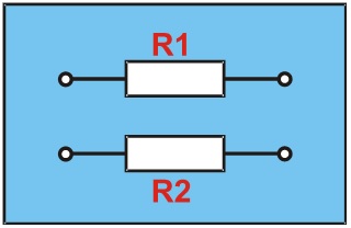
The voltage drop must be allowed for in both cores; thus, the total resistance (R) of the twin-core cable is R = R1 + R2. |
A circuit diagram of a voltage drop in twin-core cable:
|
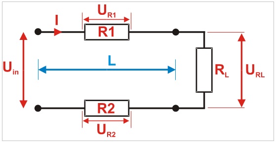
where: |
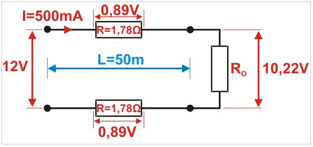
After supplying the voltage from the power supply (Uin) to the cable and connecting the load (RL), the current (I) flows through the circuit resulting in a voltage drop (UR1 + UR2) across the cable. The relationship is as follows: the output voltage at the load is reduced by the voltage drop at the cable.
|

The voltage drop (Ud) is calculated using the following formula for constant and alternating (single-phase) voltage:
|
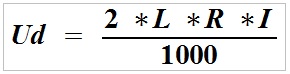
where: |
Voltage drop does not depend on the input voltage but on the current input, core length and resistance. |
The vast majority of CCTV cameras have a variable current input. The current input increases at night with the IR illuminator; for example, the power input during the day is 150 mA, whereas during the night it is 600 mA. The camera should not be supplied with higher voltage to compensate the loss at the power supply cable, since the voltage drop varies. For a long power supply cable with the IR illuminator on, the supply voltage will be sufficient, however, with the IR illuminator off, the current input will decrease, increasing the voltage at the load, which may result in camera damage. |
The resistance of a single core in Ω/km must be known to calculate the voltage drop. The calculation methods are discussed in the next section. The table shows data for selected cross-sectional areas of the core. |
|
Example
|

The calculations show that the voltage drop at the twin-core cable is 1.78 V (2 x 0.89 V) - a total voltage drop across both cores. The voltage at the load will be reduced to:
|
A percentage voltage loss at the power supply cable can be easily calculated using the following formula:
|

where: |
After substituting the formula, the percentage voltage loss at the load, i.e. the voltage loss at the power supply line can be calculated.
|
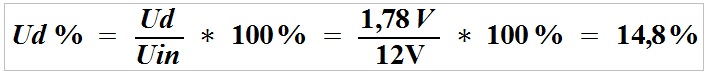
The voltage drop, in particular at low supply voltage is a serious issue. With an increase in the supply voltage, the voltage drop across the cable will be the same, but the percentage voltage drop at the load will be lower. |
Example
|

Voltage loss across the power supply line:
|
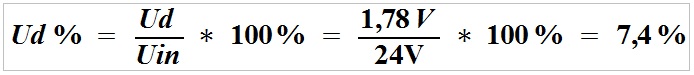
The voltage drop across the cable is 1.78 V, reducing the voltage at the load from 24 V to 22.22V, i.e. by 7.4%, which will not affect the load operation. |
Example
|
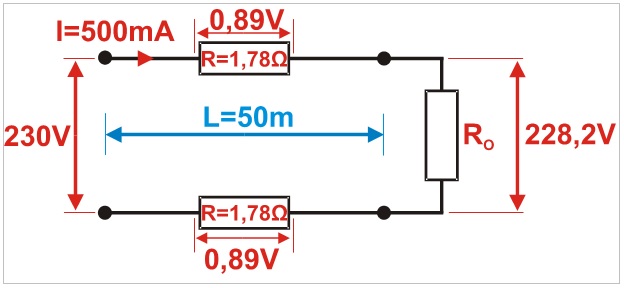
Voltage loss across the power supply line:
|
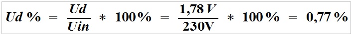
The voltage drop across the cable is 1.78 V reducing the voltage at the load from 230 V to 228.2 V, i.e. by 0.77%, which will not affect the load operation. |
Let’s analyse three power supply cases for different voltages. The voltage drop is identical in all cases and is not affected by the supply voltage. In 230 V systems, the voltage drop at the load by several volts is insignificant, however, in 12 V system, the voltage drop can be a major issue, resulting in incorrect operation of the supplied devices. |
A known cable resistance in Ω/km is required for calculations. The resistance of a single core is calculated in accordance with the second Ohm's Law. It states that the resistance of a homogeneous conductor of constant cross-section is directly proportional to its length and is inversely proportional to the area of its cross-section. |
It is expressed by a formula for calculating the resistance of a cable with a length L and a cross-sectional area S:
|
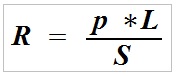
where: |
For copper, the resistivity is 0.0178 (Ω mm2/m), which means that 1 m of the cable with a cross-sectional area of 1 mm2 has a resistance of 0.0178 Ω (for pure copper). It is a rough value depending on the purity and the processing methods used. For example, cheap Chinese-made cables can be made of copper and aluminium alloys or can be doped with other metals, increasing the resistivity, resistance and voltage drop. For aluminium, the resistivity is 0.0278 (Ω mm2/m). |
Example
|
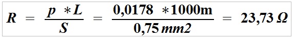
A single conductor with a length of 1000 m has a resistance of 23.73 Ω. |
Based on the above formula and the Ohm’s law, we can easily calculate the maximum current for a specific length of the conductor with a specific cross-sectional area (in mm2). We add 2 to the formula, since we will calculate the actual length of 2 conductors. |
Example |
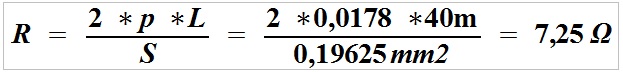
First, we will determine the conductor’s resistance.
|

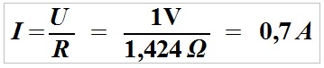
For a 12 V system, the voltage drop is 1 V, indicating that the voltage at the load is 11 V. The maximum current can be calculated from the Ohm’s law.
|
Example |
We will calculate the conductor’s resistance (UTP K5 twisted pair cable has a cross-sectional area of 0.19625 mm2):
|
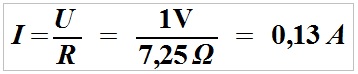
Using the Ohm’s law, we will calculate an overall voltage drop across two cores at 500 mA (0.5 A) current input.
|

I.e. the voltage drop at the supply line is 3.62 V, and the voltage at the load is 8.38 V (12 V – 3.62 V = 8.38 V). |
The maximum current for the voltage drop of 1 V for a 12 V system can also be calculated using the Ohm’s law equation, where the voltage at the load is reduced to 11 V.
|
The calculations were made for a single pair of a twisted pair cable. 2, 3 or 4 pairs of the twisted pair cable are often used to reduce the voltage drop. The pairs are connected in parallel to increase the cross-sectional area, and to reduce the line resistance, resulting in lower voltage losses. |
The calculations for the same parameters: UTP K5 twisted pair cable, power input 500 mA (0.5 A), length 30 m length, power supply 12 V: |
The table shows the maximum current that can be transmitted by the cable of a certain length and cross-sectional area, where the voltage drop at the load does not exceed 1 V. The calculations were made for two cores.
|
The next table shows the maximum current transmitted by the twisted pair cable of a certain length, where the voltage drop at the load does not exceed 1 V. The calculations were carried out for the power transmitted through 1, 2, 3 and 4 pairs of the twisted pair cable (Cat. 5 and 6).
|
A cross-sectional area of the conductor in square millimetres must be known. This parameter is not the same as the diameter. |
For thicker cables, e.g. power cables, the manufacturers and distributors give the cross-sectional area in square millimetres (mm2). For thinner cables, e.g. telecommunication, IT, a diameter of the cable is given in millimetres (mm) and must be converted into the cross-sectional area. |
The diagram shows the difference between the diameter and the cross-sectional area of the cable:
|
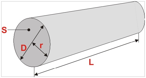
where: |
Area of the cross-section:
|
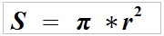
or
|

π – a mathematical constant = 3.14 |
Example
|

or
|
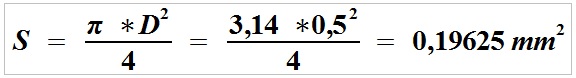
A cable with the diameter 0.5 mm has a cross-sectional area of 0.19625 mm2. |
Summary |
The main factors affecting the voltage drop: |

