dBi - antenna gain (‘G’) expressed in dBi shows a value in decibels by which the antenna gain is higher than that of a hypothetical isotropic antenna assuming that both antennas are fed with the same power.
It is a theoretical value, since the isotropic antenna does not exist and cannot be designed or constructed. Thus, the value can be calculated or expressed in theoretical terms only.
What are the origins of the term ‘isotropic’? Isotropy and isotropic from Greek ‘isos’ meaning ‘equal’ or ‘same’ and ‘trópos’ meaning ‘sense’ or ‘turn’. In science, the term is used to define the features of objects showing identical and uniform properties in all directions.
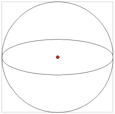
Theoretically, the isotropic antenna is an infinitesimally small point in space, radiating ideally uniformly (isotropically) in each direction in space, without reflections and losses (its radiation characteristics is spherical).
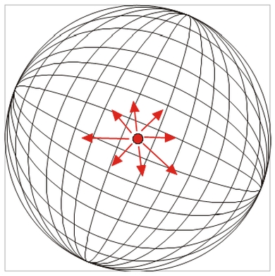
The following diagrams shows the isotropic antenna:
as a point in space
as a radiating point in space
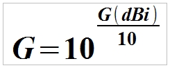
The following equation is used to calculate power gain of the isotropic antenna:
G(dBi) = 10log(G)
G(dBi) – power gain of the isotropic antenna expressed in decibels (G) – how much stronger the antenna transmits or receives signal compared to the isotropic antenna (in a linear scale).
Converted equation:
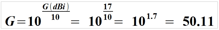
Example. Let’s calculate how much stronger a 17 dBi antenna receives (transmits) the signal the compared to the isotropic antenna.
17 dBi antenna will receive (transmit) the signal 50.11 times stronger than the isotropic antenna.
Gain of the isotropic antenna is = 0 dBi
Remember, that the half-wave dipole has a theoretical gain of 2.15 dB greater compared to the isotropic antenna (because the dipole field intensity in a given direction is greater by 2.15 dB or 1.64 times than the intensity of the isotropic antenna):
G(dBi) = G(dBd) + 2.15 dB
G(dBd) - power gain of half-wave dipole antenna
Example. Let’s consider an 8 dBi antenna and calculate its gain compared to the half-wave dipole.
G(dBd) = G(dBi) – 2.15 = 8 dBi - 2.15 = 5.85 dBd
dBi unit and definition of an isotropic antenna used in E.I.R.P. calculation is a key parameter used in design and calculations of WLAN and satellite link parameters.
E.I.R.P. (Effective Isotropic Radiated Power) - is an equivalent effective isotropic radiated power defined as a power that would have to be radiated by a hypothetical isotropic antenna to achieve identical signal level in the direction of maximum radiation of a specific antenna.”
In accordance to Polish and EU regulations, the maximum power that can be used to transmit in the specific WLAN frequency range (exceeding the power means that you are breaking the law):
2400,0 – 2483,5 MHz (2.4 GHz band) - power up to 100 mW E.I.R.P. (20 dBm),
5150 – 5350 MHz (5 GHz band) - power up to 200 mW E.I.R.P. (23 dBm) - for indoor use only,
5725 – 5875 MHz (5 GHz band) - power up to 1000 mW E.I.R.P. (30 dBm).
Consider the following to prevent E.I.R.P. thresholds from being exceeded:
cable type, length and attenuation at operating frequency and connector attenuation,
antenna power gain.
Remember, that the Access Points manufacturers often specify the transmitter power in E.I.R.P. which means that the device conforms to the regulations when using an external or built-in antenna only. For custom WLAN applications, a simple calculation will verify if the signal power meets the requirements.
For a system including a transmitter (e.g. a wireless router), cable and antenna, E.I.R.P. is calculated from the following formula:
E.I.R.P. = P – l x Tk + Gi
P – transmitter power in dBm l – cable length in metres Tk – attenuation for 1 metre of cable at operating frequency of the transmitter Gi - power gain of the isotropic antenna in dB
To simplify:
E.I.R.P. = transmitter power (dBm) + antenna gain (dBi) – cable attenuation (dB) – connector attenuation (dB)
To simplify, attenuation of a single connector is = 0.5 dB
Example. WLAN operating at 2,4 GHz band:
16 dBm access point,
8 dBi omnidirectional antenna,
8 metre cable TRI-LAN-240 (attenuation for 2.4 GHz is 0.4 dB / metre), i.e. 8 x 0.4 dB = 3.2 dB,
two connectors – attenuation + 2 x 0.5 dB = 1 dB.
Calculation:
E.I.R.P. = 16 dBm + 8 dBi – 3,2 dB – 1 dB = 19,8 dBm (i.e. the power level meets the requirements - less than 20 dBm).
Example: for a 13 dBi gain antenna:
E.I.R.P. = 16 dBm + 13 dBi – 3,2 dB – 1 dB = 24,8 dBm (i.e. exceeded by 4,8 dBm!)
Remember, not all access points reduce the output power. Thus, it is better to use a high gain antenna and a low power transmitter than a low gain antenna and a high power transmitter. The devices operate not only in transmission, but also reception mode, and thus the sensitivity of the receiver is also important.
Net:
0.00
EUR
Gross:
0.00
EUR
Weight:
0.00
kg
This site uses cookies. More information about using by us cookie files, their usage and how to modify the acceptance of cookie files, can be found by pressing
link
 English
 Български
 Český
Český Dansk
Dansk Deutsch
 Eesti
Eesti Ελληνικά
 Español
 Français
 Italiano
 Latviešu
  Lietuvių
  Magyar
 Nederlands
 Polski
 Português
 Pусский
 Română
 Slovenski
 Slovenský
 Suomi
Suomi Svenska
 EUR
EUR AUD
AUD CAD
CAD CHF
CHF CZK
CZK DKK
DKK GBP
GBP HUF
HUF NOK
NOK PLN
PLN SEK
SEK USD
USD
 Home
Home Contact
 New products